
 Q2
Q2
 QIDI Box
 Plus 4
 Q1 Pro
 X-Max 3


How to Calibrate Your 3D Printer

3D printer calibration is the process of measuring what your machine actually does and correcting the firmware or slicer values until it matches what it was told to do. Work in this order: bed level and Z-offset, extruder steps, flow rate, temperature, retraction, then dimensional accuracy and acceleration. Each stage depends on the one above it being correct.
That order is the whole trick. Calibrating flow before your extruder pushes the right amount of filament, or chasing dimensional error before the bed is level, produces numbers that look precise and are wrong. Below is each stage with the test print, the measurement, and the formula.
What 3D Printer Calibration Actually Means
Calibration is not a single procedure. It is a stack of independent measurements, each one comparing a commanded value against a measured result and correcting the difference in firmware or slicer settings.
A printer can be mechanically perfect and still print badly if its extruder pushes 96 mm when told to push 100 mm, because every wall, every top surface, and every bridge inherits that 4% error. Equally, a printer with perfect firmware values prints badly if the bed is 0.3 mm out of level on one corner. Calibration is the process of removing both classes of error, one at a time, in an order where each result stays valid once you move on.
The payoff is measurable. A calibrated machine holds dimensions within roughly ±0.2 mm on a 20 mm test cube, produces consistent wall thickness, and stops generating the intermittent failures that cost you six-hour prints.

The Calibration Order, and What Each Stage Fixes
Run these seven stages top to bottom. Skipping ahead means recalibrating later, because every stage below inherits the errors of the ones above it.
| # | Stage | What it fixes | Test print | Recalibrate when |
|---|---|---|---|---|
| 1 | Bed level and Z-offset | First layer adhesion, elephant's foot, uneven first layer | First-layer patch or single-layer square | Every build plate change, nozzle change, or bed move |
| 2 | Extruder steps / rotation distance | Global over- or under-extrusion | 100 mm manual extrusion, measured with calipers | Extruder rebuild or gear replacement |
| 3 | Flow rate and filament diameter | Wall thickness, top surface gaps, dimensional bloat | Single-wall calibration cube | Every new filament brand or material |
| 4 | Nozzle and bed temperature | Layer bonding, stringing, surface finish | Temperature tower | Every new filament spool type |
| 5 | Retraction | Stringing, blobs, oozing on travels | Retraction tower / two-pillar test | Material change or hot end swap |
| 6 | Dimensional accuracy (XYZ) | Parts that don't fit, out-of-square corners | 20 mm calibration cube | Belt or motion-system service |
| 7 | Acceleration and input shaping | Ringing, ghosting, corner overshoot | Ringing / tuning tower | After adding mass to the toolhead or raising speeds |
Stages 1 through 3 are mandatory for every machine. Stages 4 and 5 are per-material. Stages 6 and 7 are the ones most people skip, and they are where the last 10% of print quality lives.
Stage 1: Bed Level and Z-Offset
A level bed and a correct Z-offset are the foundation of every other calibration, because a squashed or floating first layer changes effective extrusion for the entire print. Level first, set Z-offset second, and never reverse the order.
Clean the plate before you measure anything. Prusa's knowledge base recommends 90% isopropyl alcohol as the default cleaner for most materials, with warm water and dish soap for stubborn oil films. Fingerprint oil on a PEI sheet reads as a leveling problem and isn't one. Our bed cleaning guide covers what to use on textured versus smooth sheets.
For manual leveling, preheat the bed to printing temperature first so thermal expansion is already accounted for, then set the nozzle gap at all four corners and the centre using a feeler gauge or a sheet of paper. You want slight, consistent drag. Repeat the circuit twice — adjusting one corner moves the others. The step-by-step method is in how to level a 3D printer bed.
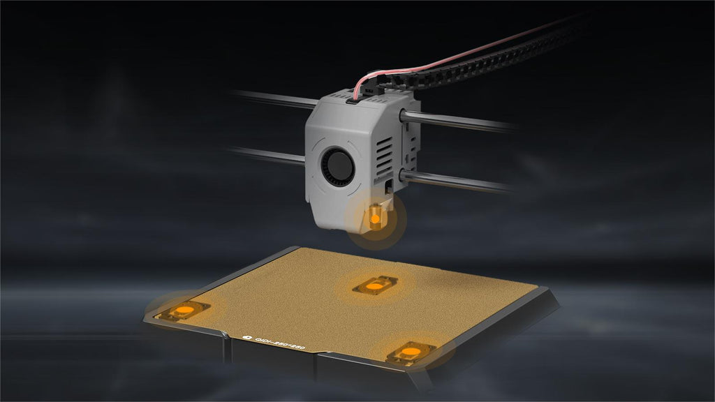
For automatic leveling, the probe builds a mesh of the surface and the firmware compensates in software. That removes the tramming step but not the Z-offset step: the probe knows the shape of the bed, not how far the nozzle tip sits below the sensor. Machines with a loadcell or strain-gauge probe that touches with the nozzle itself — the approach used on the Plus 4 and Q2 — remove most of the offset guesswork because the measurement reference is the nozzle. We break down the different probe types in the auto bed leveling guide.
Set Z-offset by printing a single-layer patch and reading it: visible gaps between lines means the nozzle is too high, a glassy translucent surface with ridges at the edges means it is too low. Adjust in 0.02–0.025 mm steps. Prusa publishes a dedicated first layer calibration routine that follows the same read-the-patch logic. If your first layer keeps failing after this, work through the first layer troubleshooting guide.
Stage 2: Extruder Steps and Rotation Distance
Extruder calibration corrects the mismatch between the length of filament the printer is told to feed and the length it actually feeds. It is measured once per extruder, not per material, and it must be right before flow rate means anything.
On Marlin-based firmware the value is steps per millimetre, set with M92 and saved with M500. The procedure: mark the filament 120 mm above the extruder inlet, command 100 mm of extrusion at a slow feedrate, measure what remains, and apply:
- New steps per mm = (current steps per mm) × (requested distance) ÷ (actual distance extruded)
On Klipper the same correction is expressed as rotation distance. Klipper's documentation specifies the method precisely: mark the filament about 70 mm from the extruder body intake, run G91 then G1 E50 F60 to push 50 mm slowly, measure the new distance, and compute rotation_distance = previous_rotation_distance × actual_extrude_distance ÷ 50, rounded to three decimals. Klipper also advises repeating the procedure if the actual distance is off by more than about 2 mm, and stresses using a slow feedrate — a fast extrusion builds pressure in the hot end and skews the reading.
Either way, verify with a second run. Two consecutive measurements within 0.5 mm of the target mean the extruder is calibrated and you can stop touching it.
Stage 3: Flow Rate and Filament Diameter
Flow rate calibration is per-filament, because spool-to-spool diameter variation and pigment loading change how much material a given feed length actually deposits. Measure filament with digital calipers at five points along the first metre; if the spread exceeds ±0.05 mm, that filament will fight you regardless of settings.
The test is a single-wall open cube — one perimeter, zero top layers, zero infill — printed at a known line width. Measure the wall in several places with calipers and average it. Then:
- New flow % = (current flow %) × (target line width) ÷ (measured wall thickness)
A 0.4 mm nozzle at 0.42 mm line width that measures 0.45 mm is over-extruding about 7%. Correct it in the filament profile, not the global printer profile, so the value follows the material. Persistent inconsistency after this points at the filament itself rather than the settings — see common filament quality problems. Consistent-diameter engineering filaments from the QIDI filament range make this step considerably shorter.
Stage 4: Temperature
Print a temperature tower and pick the lowest temperature that still gives full layer bonding. Lower is better for overhangs, bridging, and stringing; higher is better for layer adhesion and part strength. The tower makes the trade-off visible in one print instead of five.
Read the tower for three things: surface finish, stringing between the tower's separate sections, and how hard each band is to snap by hand. The band that is both strong and string-free is your number. Bed temperature follows the same logic — if adhesion is marginal, Prusa suggests raising the heatbed by 5–10 °C and reducing speed to about 75% for the first three layers before reaching for glue.
Stage 5: Retraction
Retraction calibration finds the smallest filament pull-back that eliminates stringing without causing clogs or gaps at the start of the next extrusion. Direct-drive extruders typically need 0.5–2 mm; Bowden setups need considerably more because of tube compliance.
Print a retraction tower or a simple two-pillar test and step the distance up in 0.5 mm increments, then step retraction speed in 5 mm/s increments. Stop as soon as the strings disappear — over-retracting grinds the filament and causes the missing-extrusion faults covered in this guide to mid-print extrusion stops. If strings persist at every setting, the filament is wet, not the retraction wrong; the full decision tree is in the stringing guide.

Stage 6: Dimensional Accuracy and the Motion System
Dimensional calibration checks that a commanded 20 mm becomes a measured 20 mm on every axis. Print a 20 mm calibration cube, measure X, Y, and Z with calipers, and correct the per-axis scaling in firmware only after you have ruled out the mechanical causes.
Check mechanics first, because a scaling factor applied on top of a loose belt just hides the fault. Belt tension should feel firm with very little give on the longest span. Some manufacturers publish target numbers — Prusa, for instance, documents an approximate belt status value of 250 on X and 275 on Y with a ±15 acceptable range on the MK3 series, treating readings under 240 as too loose and over 290 as too tight. Your machine's numbers will differ; the point is that belt tension is a specification, not a feeling.
Then confirm the pulley grub screws are seated on the flat of the motor shaft, and that the rails move freely by hand with no grinding. Only after that does a firmware scaling correction make sense. If the cube also shows stair-stepping or a sudden offset partway up, that is a different fault entirely — go to the layer shifting guide.
CoreXY machines are worth calling out here. Because both motors contribute to both axes, a single loose belt shows up as a skewed parallelogram rather than a simple scaling error. That's also why CoreXY platforms like the Max4 keep dimensional accuracy at speed better than bed-slinger designs — the heavy print bed doesn't accelerate back and forth. Klipper offers skew correction for the residual case where the axes are not perfectly perpendicular.
Stage 7: Acceleration and Input Shaping
Acceleration tuning finds the highest acceleration your frame tolerates before ringing appears in the corners. On Klipper firmware, input shaping raises that ceiling substantially by cancelling the specific resonant frequency of your toolhead.
Klipper's resonance compensation documentation gives a concrete ringing-test recipe: run the tuning tower with START=1500 STEP_DELTA=500 STEP_HEIGHT=5, which prints acceleration bands beginning at 1500 mm/s² and rising 500 mm/s² every 5 mm of height. Print the test at 0.2 or 0.25 mm layer height, keep external perimeters around 80–100 mm/s, and hold minimum layer time to at most 3 seconds. The docs also note that square_corner_velocity defaults to 5.0 mm/s, and that a measured resonance below roughly 20–25 Hz means the frame itself needs stiffening rather than more software compensation.
QIDI machines ship on a Klipper fork, so these tuning tools are available through the printer interface and QIDI Studio rather than needing a separate install. Speed is only usable when the motion system is calibrated behind it — we tested where that ceiling sits in FDM printing at 600 mm/s.
Calibration Diagnostic Table: Symptom to Stage
Match what you see on the part to the calibration stage that owns it. This is the fastest way to avoid recalibrating things that were never wrong.
| Symptom | Likely uncalibrated stage | How to confirm | Fix |
|---|---|---|---|
| First layer lines have gaps between them | Z-offset too high | Single-layer patch shows separate ropes, not a fused sheet | Lower Z-offset in 0.02 mm steps until lines merge |
| First layer is glossy with ridges at the edges | Z-offset too low | Nozzle leaves a translucent, scraped surface | Raise Z-offset in 0.02 mm steps |
| Good in the centre, poor at one corner | Bed level / mesh | Print four 20 mm patches at the plate corners and compare | Re-tram manually or rerun the auto mesh after cleaning the plate |
| Walls thicker than the set line width everywhere | Flow rate or extruder steps | Single-wall cube measures over target by more than 0.03 mm | Recalculate flow; if error is over 5%, redo extruder steps first |
| Gaps in top surfaces, visible infill through the skin | Under-extrusion (flow or diameter) | Manual 100 mm extrusion comes up short | Correct extruder steps, then re-measure filament diameter |
| Cube measures 20.3 mm on X and Y, 20.0 mm on Z | Dimensional accuracy — but check mechanics first | Repeat with a fresh cube; consistent error means scaling | Tension belts and check pulley screws, then apply axis scaling |
| Corners show ghost echoes of features | Acceleration / input shaping | Ringing appears after sharp corners and fades along the wall | Run the tuning tower; set max acceleration below the band where ringing starts |
| Fine strings between separate parts | Retraction or temperature | Retraction tower shows the string threshold | Increase retraction 0.5 mm at a time; drop nozzle 5 °C if it persists |
| Base of the print bulges outward | Z-offset plus bed temperature | Only the first two or three layers are affected | Raise Z-offset slightly, lower bed temperature 5 °C, enable elephant foot compensation |
| Dimensions drift between prints on the same file | Nothing is calibrated wrong — check mechanics | Rock the bed and toolhead by hand for play | Tighten frame screws and carriage eccentric nuts before recalibrating |
How Often to Recalibrate
Run a basic calibration check every few months or every 100–200 hours of printing, and immediately after any hardware change. Not every stage needs the same interval.
| Trigger | What to redo |
|---|---|
| New filament spool, same brand and material | Nothing — spot-check the first layer |
| New filament brand or material | Flow rate, temperature, retraction |
| Nozzle change | Z-offset, then flow rate |
| Build plate swap | Z-offset, and rerun the bed mesh |
| Extruder or hot end rebuild | Extruder steps, then flow rate, then Z-offset |
| Belt or motion-system service | Dimensional accuracy, then acceleration |
| Printer moved to a new location | Bed level and frame screw check |
| Every 100–200 print hours | Full pass, stages 1 through 7 |
Keep a log. Date, stage, the old value, the new value, and the test print you used. When quality drifts three months later, the log tells you what changed instead of forcing you to start from scratch. The RepRap calibration wiki is a useful companion reference if you want to expand the log into a full per-machine record.
Verifying the Whole Machine in One Print
The fastest single check of a calibrated printer is a 3DBenchy. Its hull tests bridging, its chimney tests small-feature cooling, its bow tests overhangs, and its dimensions are published, so you can measure rather than guess. We cover exactly which measurement means what in the 3DBenchy interpretation guide.
If the Benchy shows a defect you can't place, start from the general troubleshooting guide and work back to the responsible stage. For surface-level artefacts specifically, reducing visible layer lines covers the finishing side of the same problem. And when the machine is calibrated but you want to push it, a printer with a rigid frame and a properly tuned motion system holds its calibration far longer than one that needs re-tramming every week.
Frequently Asked Questions About 3D Printer Calibration
How often should I calibrate my 3D printer?
Run a full calibration pass every 100–200 print hours or every few months, whichever comes first, and recalibrate immediately after a nozzle change, extruder rebuild, build plate swap, or belt service. Flow rate and temperature should be redone for every new filament brand or material.
What order should I calibrate my 3D printer in?
Bed level and Z-offset, extruder steps, flow rate, temperature, retraction, dimensional accuracy, then acceleration. Each stage assumes the ones above it are correct. Calibrating flow before extruder steps, for example, bakes the extruder's error into your flow number and you will have to redo both.
How do I calibrate extruder steps per mm?
Mark the filament 120 mm above the extruder inlet, command 100 mm of extrusion at a slow feedrate, and measure what is left. New steps per mm equals current steps per mm times 100 divided by the distance actually extruded. On Klipper the equivalent value is rotation distance, calibrated by extruding 50 mm at F60 and scaling the previous value by the measured result.
Why is my calibration cube not 20 mm?
Check mechanics before firmware. Loose belts, unseated pulley grub screws, and a bed or carriage with play all produce dimensional error that a scaling factor only masks. If the error is repeatable across several cubes and the mechanics are tight, then apply a per-axis scaling correction in firmware.
Do I need to calibrate a 3D printer that came pre-assembled?
Yes, but less of it. Pre-assembled machines usually arrive with extruder steps and dimensional accuracy set at the factory, so your work is mostly Z-offset, per-material flow, and temperature. Verify the factory numbers once with a single-wall cube and a calibration cube so you know your baseline.
What is the difference between bed leveling and Z-offset?
Bed leveling makes the plate parallel to the toolhead's motion plane, or maps its deviation so firmware can compensate. Z-offset sets how far the nozzle tip sits above that plane. Auto bed leveling handles the first and not the second, which is why a printer with a perfect mesh can still lay down a bad first layer.
How do I calibrate flow rate?
Print a single-wall open cube with one perimeter and no top layers, measure the wall in several places, and average it. New flow percentage equals current flow percentage times target line width divided by measured wall thickness. Store the result in the filament profile rather than the printer profile, because flow is a material property.
Can bad calibration damage a 3D printer?
Some of it can. A Z-offset set too low drives the nozzle into the build plate and can gouge the sheet or deform the probe mount; over-tight belts load motor bearings; and motor current set too high overheats drivers. Most calibration mistakes only cost you prints, but those three cost hardware, so change them in small steps.
- What 3D Printer Calibration Actually Means
- The Calibration Order, and What Each Stage Fixes
- Stage 1: Bed Level and Z-Offset
- Stage 2: Extruder Steps and Rotation Distance
- Stage 3: Flow Rate and Filament Diameter
- Stage 4: Temperature
- Stage 5: Retraction
- Stage 6: Dimensional Accuracy and the Motion System
- Stage 7: Acceleration and Input Shaping
- Calibration Diagnostic Table: Symptom to Stage
- How Often to Recalibrate
- Verifying the Whole Machine in One Print
- Frequently Asked Questions About 3D Printer Calibration
- How often should I calibrate my 3D printer?
- What order should I calibrate my 3D printer in?
- How do I calibrate extruder steps per mm?
- Why is my calibration cube not 20 mm?
- Do I need to calibrate a 3D printer that came pre-assembled?
- What is the difference between bed leveling and Z-offset?
- How do I calibrate flow rate?
- Can bad calibration damage a 3D printer?
Recommended products