
 Q2
Q2
 QIDI Box
 Plus 4
 Q1 Pro
 X-Max 3


Is the layer pattern too obvious? Learn a move to easily deal with it

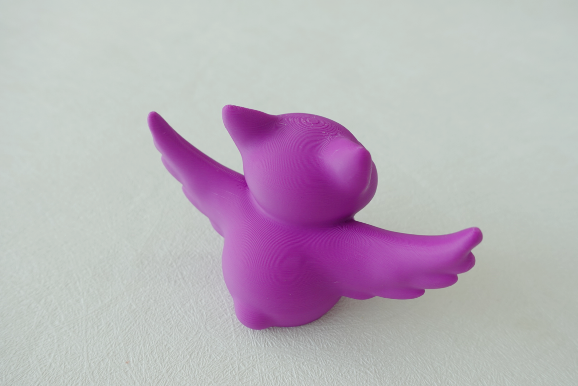
To reduce visible layer lines on an FDM print, drop your layer height to 0.12 mm or turn on adaptive layer height, slow outer walls to 25–40 mm/s, tune pressure advance, and hide the Z-seam on a back edge. Those four changes fix layer lines at the print stage, before you ever pick up sandpaper.
I print a lot of display pieces, and I got tired of sanding. So this guide is about what I actually change in the slicer to stop layer lines from showing up in the first place. If the part is already printed and you want to smooth it after the fact, that is a different job — the post-processing selection guide covers sanding, vapour smoothing and paint. This one stays on the printer side.
Why layer lines show up at all
Layer lines are the horizontal ridges left where each extruded layer meets the next, and they exist because FDM builds parts by stacking rounded beads of plastic. A bead squashed onto the layer below is flat in the middle and curved at the edges, so every layer boundary is a small valley. You can make those valleys shallower and closer together, but with fused filament fabrication you cannot make them disappear.
The nastier version is stair-stepping. Stair-stepping is the terracing you get on shallow slopes and domes, where each layer steps sideways by a visible amount because the surface angle is close to horizontal. A 10-degree slope at 0.2 mm layer height steps sideways by over 1 mm per layer. That is the "step-like" pattern that ruins the top of a curved model, and it is the one adaptive layer height was invented for.
The third thing people call layer lines is not layer lines at all — it is ringing, the repeating echo of a corner that shows up 3–10 mm past the corner. That is vibration, not layer stacking, and lowering layer height does nothing for it.
Setting 1: layer height, and what it actually costs
Layer height is the single biggest lever on how visible the lines are, and the relationship is close to linear — half the layer height, roughly half the ridge depth. Here is what I use, and what it costs me in time on a typical 120 mm display print.
| Layer height | Line visibility on walls | Print time vs 0.20 mm | What I use it for |
|---|---|---|---|
| 0.28 mm (Draft) | Obvious at arm's length | −30% | Test fits, jigs, throwaway prototypes |
| 0.20 mm (Standard) | Clearly visible up close | baseline | Functional parts nobody looks at |
| 0.16 mm (Optimal) | Visible only at raking light | +25% | My default for anything I keep |
| 0.12 mm (Fine) | Faint; feels smooth to a fingertip | +65% | Display models, painted props |
| 0.08 mm (Extra Fine) | Barely detectable | +150% | Miniatures, tiny lettering only |
My honest take: 0.08 mm is almost never worth it. The gap between 0.12 and 0.08 is small enough that you need raking light to see it, and the print takes nearly twice as long. I ran a 14-hour dragon at 0.08 mm once to prove a point, and next to the 0.12 mm copy I could not reliably tell them apart. Stop at 0.12 mm.
Setting 2: adaptive layer height, the one that pays for itself
Adaptive layer height (called Variable Layer Height in QIDI Studio) lets the slicer assign thin layers to curved or sloped regions and thick layers to straight vertical walls, so you spend print time only where it improves the surface. It is the highest-value setting in this whole guide, because it targets stair-stepping specifically — which is where the ugly banding actually lives.
Here is the workflow in QIDI Studio. Slice the model first and look at the top; the default profile leaves heavy texture on curved regions.

The blunt fix is to change the process profile. The number in front of each profile name is the layer height, so switching "0.20mm Standard" to "0.12mm Fine" halves the ridge depth everywhere.


Re-slice and the texture on the top of the model is visibly weaker. The catch is the number in the corner: the same model now takes substantially longer.


So instead, select the model and open Variable Layer Height in the toolbar.

Click Adaptive, then click Smooth two or three times to soften the transitions between zones. Green marks regions the slicer has thinned; orange marks regions it has left thick.

You can also paint the profile by hand in the preview strip on the right. Left-click drags the layer height down (green), right-click pushes it up (orange). I use this when the slicer misses a shallow chamfer that I care about.

Re-slice. The texture on the curved top is close to the full 0.12 mm result, but the time penalty is a fraction of it.


Before and after on the same model — this is what the difference looks like on the actual print.


Prusa's variable layer height documentation covers the same feature in PrusaSlicer if you want a second reference on how the algorithm picks its zones.
Setting 3: outer wall speed and flow consistency
Outer wall speed controls how consistently the extruder can hold pressure through corners, and inconsistent pressure shows up as bulges and thin spots that read as bad layer lines. I run outer walls at 25–40 mm/s regardless of how fast the rest of the part goes.
These are the numbers on my machine that made the biggest visible difference:
- Outer wall speed: 30 mm/s for display parts, 50 mm/s when I don't care.
- Outer wall acceleration: capped at 1,000–2,000 mm/s², separate from the 20,000+ the machine can do on infill.
- Wall order: inner walls first, then outer. The outer wall lands against a solid backing instead of open air.
- Wall loops: 3 minimum. Two walls means every dimensional wobble shows on the outside.
- Pressure advance / linear advance: calibrate it. Uncalibrated PA is what causes the bulge right after every corner. Klipper's pressure advance documentation has the tower test procedure.
My own screw-up here: I spent a week chasing "layer lines" on a curved vase that turned out to be uncalibrated pressure advance. The banding lined up perfectly with the seam because pressure was spiking at every travel restart. Ten minutes on the PA tower fixed what a week of layer-height fiddling did not. Run the basic calibration sequence before you conclude anything about surface quality.
Setting 4: the Z-seam
The Z-seam is the vertical scar where the nozzle starts and stops each perimeter loop, and on a round model an aligned seam stacks every one of those scars into a single visible line. It is the defect people most often mistake for a layer line problem.
Options, in the order I try them:
- Aligned + rear: puts the seam on one back edge. Best for anything with an obvious "back".
- Seam painting: manually paint the seam into a corner or a detail line where it disappears. This is the one that actually solves it on organic models — see the seam optimisation guide for the QIDI Studio workflow.
- Scarf joint / staggered seam: ramps the start and end overlap so there is no abrupt step. Slower, but the cleanest result on cylinders.
- Random: scatters the seam. Trades one visible line for surface-wide speckle. I rarely like the result.
Setting 5: temperature, cooling and material choice
Printing 5–10 °C too hot makes layers sag into each other and blurs the surface; printing too cold leaves the ridges sharp and unbonded. Start at the middle of the filament's stated range and run a temperature tower — it takes 40 minutes and it settles the question for that spool.
Material choice is a shortcut most people miss. Matte and textured filaments diffuse light across the surface and genuinely hide layer lines that gloss filaments advertise. A matte PLA at 0.20 mm often looks smoother than a glossy PLA at 0.12 mm, at a third of the print time. The rest of the QIDI filament range lists finish alongside the mechanical specs.
Diagnose before you change anything
Different surface defects get called "layer lines" and they need different fixes, so identify what you're actually looking at first. Hold the part under a light source at a shallow angle — raking light shows everything.
| What you see | What it is | Root cause | Fix |
|---|---|---|---|
| Even horizontal ridges, uniform all the way up | Normal layer lines | Layer height | Drop to 0.12–0.16 mm, or use adaptive layer height |
| Terracing on curves and shallow slopes | Stair-stepping | Layer height vs surface angle | Adaptive layer height; reorient the part |
| Repeating echo 3–10 mm past every corner | Ringing / ghosting | Frame resonance | Input shaping; cap outer wall acceleration |
| One vertical scar up the whole part | Z-seam | Perimeter start point stacking | Paint the seam, or aligned + rear, or scarf joint |
| Bulge immediately after each corner | Pressure lag | Uncalibrated pressure advance | Run the PA tower and set the value per filament |
| Bands at a fixed repeating spacing (e.g. every 2 or 4 mm) | Z-wobble | Bent leadscrew or binding Z axis | Mechanical — compare the band pitch to leadscrew pitch |
| Random thick and thin layers, no pattern | Inconsistent extrusion | Wet filament, partial clog, worn drive gear | Dry the spool, clean the nozzle, inspect the extruder |
| Glossy patches next to matte patches | Cooling variance | Uneven part cooling airflow | Check the part fan and duct; raise minimum layer time |
The pitch of the pattern is the most useful clue you have. Uniform lines are a settings problem. Anything periodic is mechanical, and the period usually points straight at the component causing it.
When it is the machine, not the settings
If lines are uneven — some thick, some thin, in a repeating pattern up the wall — the problem is mechanical and no slicer setting will fix it. Check for Z-wobble from a bent leadscrew, belt tension, and loose eccentric nuts on the gantry.
Ringing next to corners is resonance, and the fix is input shaping: the firmware measures the frame's resonant frequency and pre-compensates the motion so the ringing cancels. Klipper's resonance compensation guide explains the accelerometer procedure. Machines built around a rigid CoreXY frame with input shaping already tuned, like the QIDI Q2 or the larger Max4, hold surface quality at speeds where a bed-slinger starts to ghost. If you are shopping with surface finish in mind, the current lineup lists frame type and speed together.
My default recipe
For a display part I want to look good with zero sanding:
- 0.16 mm base layer height, Variable Layer Height on Adaptive, Smooth clicked twice
- 3 wall loops, inner walls first
- Outer wall 30 mm/s, outer wall acceleration capped at 1,500 mm/s²
- Pressure advance calibrated for that specific spool
- Seam painted onto a back edge, or aligned + rear
- Matte filament if the colour allows it
- Ironing on for flat top faces only — see the ironing guide
That gets me to the point where the remaining lines only show under raking light. If I need better than that, I stop fighting the printer and go sand it — the PLA sanding and polishing guide picks up from there.
Frequently asked questions
What layer height removes layer lines completely?
No layer height removes them completely, because FDM stacks rounded beads by definition. At 0.08 mm the ridges are usually below what an unaided eye picks up at normal viewing distance, but they are still there under raking light. If you need a genuinely line-free surface you need post-processing — sanding, filler primer, or vapour smoothing for ABS and ASA.
Does slowing down the print reduce layer lines?
Slowing the outer wall specifically helps a lot; slowing the whole print mostly wastes time. Outer wall speed and acceleration determine how well the extruder holds steady pressure around corners, and that consistency is what you see on the surface. Infill and inner wall speed have essentially no effect on the visible finish, so leave those fast.
Why are my layer lines uneven instead of uniform?
Uneven banding that repeats at a fixed height up the part is almost always mechanical — a bent Z leadscrew, a binding linear rail, or a loose gantry wheel producing Z-wobble. Uniform lines are a settings problem; patterned or periodic lines are a hardware problem. Measure the spacing of the pattern and compare it to your leadscrew pitch, that usually identifies it immediately.
Is adaptive layer height worth using on every print?
It is worth it on anything with curves, domes, or shallow slopes, and pointless on a part that is all vertical walls and flat tops. On a box-shaped part every layer is the same, so the algorithm has nothing to optimise. On an organic model it can deliver most of the benefit of a 0.12 mm print for a fraction of the added time.
Does a heated chamber affect layer lines?
A heated chamber mainly affects warping and layer adhesion on high-shrinkage materials like ABS, ASA and PC rather than surface ridges directly. The indirect benefit is real though — a part that is not curling stays flat against the intended toolpath, so the lines stay evenly spaced. On PLA and PETG, which most people print for looks, chamber heat is not the variable that matters.
- Why layer lines show up at all
- Setting 1: layer height, and what it actually costs
- Setting 2: adaptive layer height, the one that pays for itself
- Setting 3: outer wall speed and flow consistency
- Setting 4: the Z-seam
- Setting 5: temperature, cooling and material choice
- Diagnose before you change anything
- When it is the machine, not the settings
- My default recipe
- Frequently asked questions
- What layer height removes layer lines completely?
- Does slowing down the print reduce layer lines?
- Why are my layer lines uneven instead of uniform?
- Is adaptive layer height worth using on every print?
- Does a heated chamber affect layer lines?
Recommended products