
 Q2
Q2




Designing 3D Printed Shelf Brackets for Maximum Load Capacity


A 3D printed shelf bracket carries load through geometry first and material second. Print it on its side so the L-shape is formed by continuous extrusions rather than stacked layers, fillet every internal corner, add a gusset and a 3 mm boss around each screw hole, and run 6 walls before you touch infill. For anything above 10 kg, move from PETG to a fibre-reinforced filament.
The Engineering Shift: From Decorative to Functional 3D Printing
For many, the journey into 3D printing begins with aesthetic models—figures, desk toys, and decorative items. However, as users transition into the "prosumer" and small-business space, the focus shifts from how a part looks to how it performs under load. Designing a 3D printed shelf bracket is a classic engineering challenge that bridges this gap. It requires a move away from "trial and error" toward a methodology grounded in structural optimization and material science.
Additive Manufacturing (AM) is used to create lightweight, end-use parts that must withstand significant mechanical stress. While a shelf bracket may seem simple, it is subject to the same physics. To achieve maximum load capacity, you must account for stress concentrations, anisotropic strength (layer-dependent weakness), and the specific thermal properties of engineering-grade filaments.
The goal is not simply to make the part "heavier" by increasing infill, but to make it "smarter" through optimized geometry. This guide explores the technical principles required to build brackets that rival injection-molded components in reliability.
The Mechanics of Failure: Why Brackets Break
Before optimizing for strength, we must understand how 3D printed parts typically fail. Unlike isotropic materials like cast aluminum or molded plastic, FDM (Fused Deposition Modeling) prints are anisotropic. This means their strength varies depending on the direction of the applied force.
1. The Z-Axis Weakness (Interlayer Adhesion)
The most common failure point in a bracket is the bond between layers. When a load is applied, it often creates a "peeling" force between the horizontal layers.
Manufacturer data makes the size of this penalty concrete. QIDI publishes 142 MPa flexural strength in XY for its PPS-CF filament against 36 MPa in Z — a 75% loss across the layer interface, measured on the same material. Independent testing across other composites lands in a similar band. The practical consequence is that a bracket printed in the wrong orientation typically fails at a fraction of the load an identical bracket carries in the right one, and no amount of infill recovers that.
2. Stress Concentrations at Sharp Corners
In mechanical part design, the most frequent failure in 3D printed brackets isn't a lack of material strength, but stress concentration at sharp 90-degree corners. These sharp transitions act as force multipliers, focusing the entire shelf load onto a single line of plastic. This leads to crack propagation and sudden mechanical failure.
3. Fastener Pull-Out
Even if the bracket body is strong, the point where it attaches to the wall or the shelf is a vulnerability. Standard 3D printed walls are often too thin to hold the threads of a screw under load, leading to the screw "pulling through" the part.
Best Filament for Shelf Brackets, by Shelf
There is no single best filament for shelf brackets, because a floating spice rack and a garage shelf holding paint tins are not the same engineering problem. Match the shelf to the row, then design to the requirements in it.
| Shelf and environment | Load per bracket | Filament | Walls / infill | Extra requirement |
|---|---|---|---|---|
| Decorative shelf, indoor, climate-controlled | Under 3 kg | PETG | 4 walls / 30% gyroid | Fillet internal corners; gusset optional |
| Bookshelf or kitchen shelf, indoor | 3–10 kg | PETG or PETG-GF | 5–6 walls / 40% | Full gusset, 3 mm boss at every screw |
| Workshop shelf, stable temperature | 10–20 kg | PET-CF | 6 walls / 40–50% | Hardened nozzle; anneal after printing |
| Garage shelf, 10–40°C annual swing | 10–20 kg | PET-CF or PET-GF | 6 walls / 50% | Creep margin matters more than peak strength |
| Heavy or long-span shelf | Over 20 kg | UltraPA-CF25 | 6–8 walls / 50% | Actively heated chamber; anneal; dry filament |
| Outdoor or unheated shed | Any | ASA, or metal | 6 walls / 50% | UV stability outranks strength outdoors |
| Above a workspace, bed, or walkway | Any | Commercial steel brackets | — | Printed parts carry no certified load rating |
The last row is not a formality. A shelf bracket is one of the few household prints where failure drops mass onto whatever is below it, so the honest recommendation for anything overhead is hardware with a published rating.
Strategic Geometry: Gussets, Fillets and Bosses
To solve these issues, we move beyond simple L-shapes and embrace engineering heuristics that distribute forces more evenly.
The Gusset
A gusset—the triangular support between the vertical and horizontal arms of the bracket—is the single most effective geometric addition. Two rules govern it:
- Thickness: make the gusset at least as thick as the wall it reinforces, and round that thickness to a whole multiple of your extrusion width so the slicer fills it with solid perimeters instead of a thin gap. The injection-moulding convention of making ribs 0.5–0.6× the wall thickness exists to avoid sink marks on a moulded surface; FDM has no sink marks, so that constraint does not carry over and a thin gusset simply gives up load capacity for nothing.
- Depth: a gusset that runs at least half the length of the horizontal arm moves the failure point away from the corner. A short stub gusset just relocates the stress concentration to its own tip.
- Tapering: a gusset that is deeper at the corner and shallower at the tip follows the bending moment diagram and saves material without giving up capacity.
Fillets: The Enemy of Stress
Replacing every sharp internal corner with a fillet (a rounded radius) is the single most effective way to increase load capacity for zero extra material. A fillet distributes the load over a larger surface area, preventing stress from bottlenecking at a single point. Use the largest radius the geometry allows; even a 2 mm fillet at the inside corner of an L-bracket makes a measurable difference.
The 3mm Boss Rule for Screw Holes
To prevent wall pull-out failures, do not rely on the standard wall thickness of your print.
- The heuristic: add a minimum 3 mm thick boss (a cylindrical reinforcement) around every screw hole.
- The benefit: the screw threads engage a solid mass of plastic rather than a few perimeters, turning a likely failure point into a structural anchor.
- The upgrade: for brackets above 10 kg, use a heat-set brass insert and a bolt rather than a screw thread cut into plastic. Bolt-bearing strength is where FDM is weakest, and metal inserts sidestep it entirely.
Material Selection: Beyond PLA
While PLA is excellent for prototyping, it is prone to creep — the tendency of a material to deform permanently under a constant load over time. QIDI's PLA data sheet lists a heat deflection temperature of 57.6°C, and creep accelerates long before that temperature is reached. A shelf bracket is the definition of a constant-load part, so engineering-grade filaments are required for anything beyond a light decorative shelf.
According to the NIST research on advanced materials for additive manufacturing, the integration of reinforcements like carbon fiber or glass fiber significantly enhances the mechanical benchmarks of thermoplastics.
High-Performance Filament Comparison
| Material | Tensile strength | Bending modulus | Heat deflection | Best use case |
|---|---|---|---|---|
| PETG Basic | 45.2 MPa | 1,720 MPa (tensile modulus) | 71.8°C | Light indoor shelves; no special nozzle needed |
| PETG-GF | 51 MPa | 2,400 MPa (tensile modulus) | 76°C | Medium indoor loads; hardened nozzle required |
| PET-CF | 72.51 MPa | 5,346 MPa | 86.7°C | High stiffness, low moisture absorption |
| PET-GF | 64.65 MPa | 3,201 MPa | 86.7°C | Impact resistance and thermal stability |
| UltraPA-CF25 | 118.19 MPa | 9,214 MPa | 196.9°C | Maximum load capacity and heat resistance |
Note: values are as published in QIDI's technical data sheets; PET-CF, PET-GF and UltraPA-CF25 bending moduli are flexural, PETG figures are tensile moduli.

For most heavy-duty household applications, PET-CF Filament is the sweet spot. It offers excellent dimensional stability and high stiffness without the moisture sensitivity of pure nylon. If you are designing for extreme environments or maximum possible load, UltraPA-CF25 (PPA-CF core) Filament provides the highest bending modulus of the group, ensuring the bracket does not sag over time. For lighter shelves, PETG-GF is the cheapest meaningful step up from plain PETG. Browse the industrial-grade composites collection for the full reinforced range.
The same material logic applies to smaller fittings. Printing replacement clips for loose window screens shows how a part that lives in a sunlit frame needs a different filament than one that stays indoors, even at a fraction of the load, and the PETG wall-mounted bracket analysis covers the lower end of this load range in detail.
Manufacturing Parameters for Maximum Strength
The hardware you use is as important as the design. High-performance materials like Carbon Fiber (CF) and Glass Fiber (GF) require specific conditions to reach their full potential.
1. Active Chamber Heating
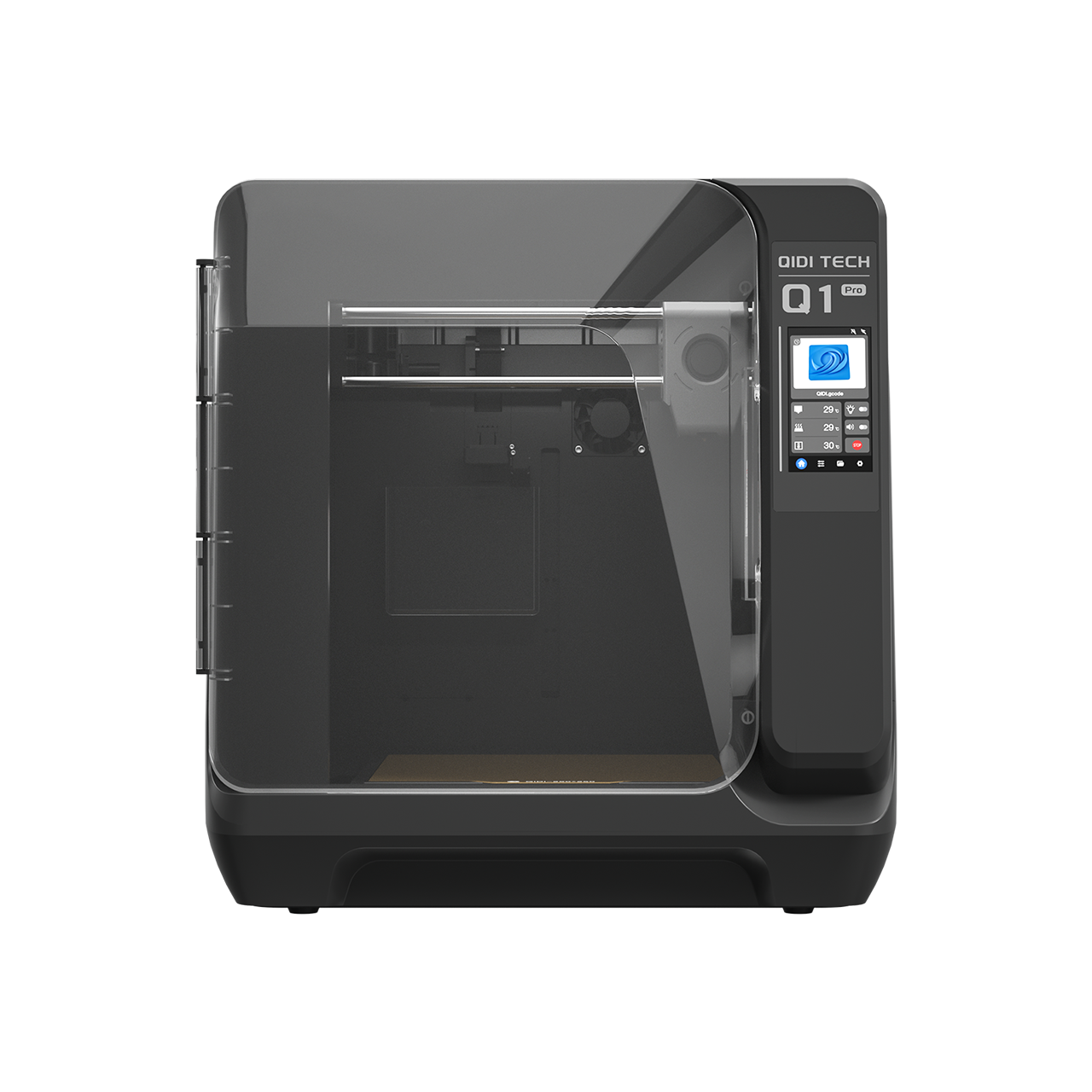
When printing with structural materials like ABS, ASA, or nylon-based composites, thermal management is non-negotiable. The QIDI Max4 3D Printer features a 65°C active chamber heating system, as do the Plus 5 and the Q2; the entry-level Q2C has a flame-retardant enclosure but no chamber heater, which limits it to the PETG rows of the table above.
- The benefit: a consistent chamber temperature throughout the build significantly improves interlayer adhesion. By reducing thermal shock between layers, you create a more monolithic part that is less likely to delaminate under stress — which matters most in exactly the direction FDM is weakest.
2. Slicing for Strength: Walls Over Infill
A common misconception is that 100% infill makes a part unbreakable. In reality, adding wall loops (perimeters) is far more effective.
- The logic: bending stress peaks at the outer skin of a part. Increasing wall loops to 6 or 8 creates a thick structural shell that carries most of the load. Infill exists to support those walls and prevent buckling.
- Infill patterns: use gyroid or 3D honeycomb. These provide near-equal strength in all directions, unlike grid or lines which are weak when loaded from the side. The infill pattern and density guide compares them, and the minimum wall thickness guide sets the lower bound for load-bearing features.
3. Orientation Beats Everything
Print the bracket lying on its side so the L-shape is formed by continuous extrusions running around the corner, not by layers stacked across it. This is the highest-leverage decision in the whole process and it costs nothing. The model placement and slicing guide walks through how to reason about orientation for a given geometry.
4. The Power of Annealing
For semi-crystalline reinforced materials like PET-GF Filament, the manufacturing process doesn't end when the printer stops.
- The process: place the printed bracket in an oven at 80–100°C for 4–6 hours, supported so it cannot sag.
- The result: annealing relieves internal printing stresses and increases crystallinity, which raises stiffness and heat deflection temperature. Published work on FDM post-treatment confirms that annealing temperature measurably changes tensile and flexural strength, though the size of the gain depends on the polymer and the schedule. QIDI's own data illustrates the scale: PAHT-CF's heat deflection temperature rises from 84.8°C unannealed to 190.7°C annealed.
- The caution: annealing can shrink and distort a part. Anneal a test copy and measure it before committing a fitted bracket.
Validation and Safety Factors
In a professional engineering environment, we would use Finite Element Analysis (FEA) to simulate loads. For the home user or small business, we use a factor of safety.
Logic summary: printed parts vary with moisture level, nozzle wear, ambient temperature and orientation. That variability, plus creep over months of constant load, is what the safety factor is buying you.
- Use a factor of 5 for shelving: if you need a bracket to hold 10 kg, design and test it to hold 50 kg. In other words, the design load should be five times the working load.
- Why so high? It absorbs the 40–75% strength loss that a mis-oriented layer interface can introduce, plus creep accumulated over months or years of continuous loading.
- Lower factors for lower stakes: a factor of 3 is defensible for hand-height hooks and light fittings, as covered in the wall hook material guide. Shelving sits higher and holds more, so it gets the larger margin.
If you are unsure of the capacity, conduct a destructive test on a sacrificial unit. Gradually add weight until it breaks, then divide that breaking weight by five to find your safe working load. Test the exact geometry, material, orientation and wall count you intend to use — a test on a different print profile tells you nothing about the bracket you are actually mounting.
Summary of Key Takeaways
Building a high-capacity shelf bracket is an exercise in managing the unique characteristics of 3D printing. By following these principles, you can create parts that are functional and predictable:
- Prioritize orientation: print the bracket on its side so the L-shape is formed by continuous strands, not stacked layers.
- Eliminate sharp corners: use large fillets at every internal junction to prevent stress concentration.
- Size the gusset properly: at least as thick as the wall it reinforces, and at least half the arm length deep.
- Reinforce attachment points: use the 3 mm boss rule, and heat-set inserts above 10 kg.
- Choose the right filament: PET-CF for stiffness, UltraPA-CF25 for maximum load, PETG for light indoor shelves.
- Leverage hardware: use a 65°C actively heated chamber to maximise interlayer bond strength.
- Post-process: anneal glass- or carbon-filled parts, then re-measure before mounting.
Frequently asked questions
How much weight can a 3D printed shelf bracket hold?
There is no universal figure, because capacity is set by geometry, orientation, wall count, fastener and material together — the same design can differ several-fold between a good and a bad print orientation. The defensible method is to destructively test one sacrificial copy of your exact design and divide the breaking load by five. Any published number that omits the print profile is not transferable to your bracket.
What is the best filament for shelf brackets?
PETG for light indoor shelves under 3 kg, PETG-GF or PET-CF for 3–20 kg, and UltraPA-CF25 above that or where heat is involved. PLA should not be used for any permanently loaded shelf: its 57.6°C heat deflection temperature and susceptibility to creep mean it sags under constant load long before it breaks.
How should a 3D printed shelf bracket be oriented on the plate?
Lying on its side, so the vertical arm, corner and horizontal arm are all formed by continuous extrusions in the same plane. Printed upright, the load tries to peel the layers apart at the corner, which is where manufacturer data shows losses of 40–75% versus the in-plane direction.
Does infill density matter more than wall count?
No. Bending stress concentrates at the outer skin, so wall loops carry most of the load in a bracket. Going from 4 to 6 walls buys more capacity than going from 30% to 60% infill, and prints faster. Use 40–50% gyroid infill and spend the rest of your material budget on perimeters.
Should I anneal a printed shelf bracket?
For glass- or carbon-filled semi-crystalline filaments, yes — annealing relieves internal stress and raises stiffness and heat deflection temperature. For PETG and PLA the gain is smaller and the distortion risk is higher. Always anneal a test copy first and measure it, because annealing can shrink a part enough to ruin a fitted mounting hole pattern.
Disclaimer: This article is for informational purposes only. The load capacity of 3D printed parts depends on numerous variables including print settings, material quality, and environmental conditions. Always perform independent load testing for critical applications. 3D printed parts may fail unexpectedly; do not use them for overhead storage or in applications where failure could result in injury or significant property damage.
Sources
- The Engineering Shift: From Decorative to Functional 3D Printing
- The Mechanics of Failure: Why Brackets Break
- 1. The Z-Axis Weakness (Interlayer Adhesion)
- 2. Stress Concentrations at Sharp Corners
- 3. Fastener Pull-Out
- Best Filament for Shelf Brackets, by Shelf
- Strategic Geometry: Gussets, Fillets and Bosses
- The Gusset
- Fillets: The Enemy of Stress
- The 3mm Boss Rule for Screw Holes
- Material Selection: Beyond PLA
- High-Performance Filament Comparison
- Manufacturing Parameters for Maximum Strength
- 1. Active Chamber Heating
- 2. Slicing for Strength: Walls Over Infill
- 3. Orientation Beats Everything
- 4. The Power of Annealing
- Validation and Safety Factors
- Summary of Key Takeaways
- Frequently asked questions
- How much weight can a 3D printed shelf bracket hold?
- What is the best filament for shelf brackets?
- How should a 3D printed shelf bracket be oriented on the plate?
- Does infill density matter more than wall count?
- Should I anneal a printed shelf bracket?
- Sources
Рекомендуемые продукты