
 Q2
Q2
 QIDI Box
 Plus 4
 Q1 Pro
 X-Max 3


What Is FDM 3D Printing?

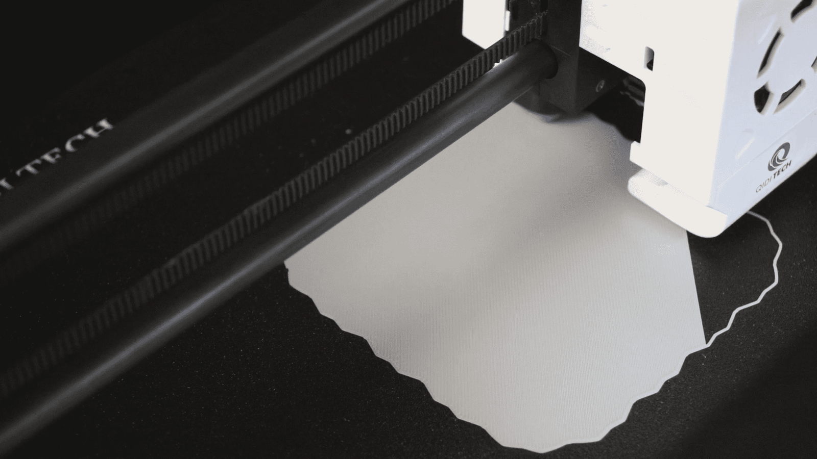
FDM 3D printing is an additive manufacturing process in which a thermoplastic filament is melted in a heated nozzle and deposited layer by layer onto a build platform, where it cools and fuses to the material beneath it. It is the most widely used 3D printing technology in the world, and every desktop filament printer uses it.
This page covers the process itself: how it works stage by stage, what the machine is made of, what the resulting parts are actually like, and how FDM compares with the other additive processes you will run into.
What Is FDM 3D Printing?
Fused deposition modeling (FDM) is a material extrusion process that builds parts from a continuous thermoplastic filament, melting it just above its softening point and laying it down along paths computed from a 3D model. Each deposited bead partially remelts the layer below, so adjacent layers weld together as the part grows upward.
The technology was developed by S. Scott Crump, co-founder of Stratasys, in 1988. Stratasys holds the FDM trademark, and its patent expired in 2009 — which is precisely why the desktop 3D printing market exists in its current form. Members of the RepRap project coined the alternative term fused filament fabrication (FFF) to have an acronym free of trademark constraints. The two terms describe the same process; if you want the full naming story and which vendors use which label, we cover it separately in FDM vs FFF. This article stays on the process.
In the ISO/ASTM classification of additive manufacturing, FDM sits in the material extrusion category — one of seven recognised process families that also include vat photopolymerisation, powder bed fusion, and binder jetting. Standards work in this area is coordinated in part by NIST's additive manufacturing programme.

How FDM 3D Printing Works: The Seven Stages
Every FDM print follows the same sequence: model, slice, prepare, print, cool, support removal, finish. The table below gives each stage, what physically happens, and the failure that stage is responsible for.
| Stage | What happens | Output | What goes wrong here |
|---|---|---|---|
| 1. Model | The part is designed in CAD or downloaded as a mesh. | STL, 3MF, or OBJ file | Non-manifold geometry, inverted normals, wall thicknesses below nozzle diameter. |
| 2. Slice | Slicing software cuts the model into horizontal layers and generates toolpaths and temperatures. | G-code | Wrong layer height for the nozzle, missing supports, unrealistic speed for the hotend's flow rate. |
| 3. Prepare | Filament is loaded, the bed and nozzle preheat, and the printer probes the bed for levelness. | Machine at setpoint, bed mesh stored | Contaminated build surface, wrong Z offset, damp filament. |
| 4. Print | The nozzle traces each layer while the platform or gantry indexes one layer height per pass. | Part growing on the plate | Under-extrusion, layer shifts, warping, nozzle clogs. |
| 5. Cool and fuse | Extruded plastic solidifies within seconds; the part cooling fan controls how fast. | Bonded layers | Too much cooling on ABS causes layer splitting; too little on PLA causes drooping overhangs. |
| 6. Remove supports | Sacrificial structures under overhangs are broken or dissolved away. | Bare part | Surface scarring, broken thin features. |
| 7. Post-process | Optional sanding, vapour smoothing, annealing, painting, or insert installation. | Finished part | Annealing without a fixture causes shrinkage and distortion. |
Stage 2 is where most of the decisions live. Layer height, wall count, infill, temperatures, and speeds are all set there, and they determine far more about the outcome than the choice of printer does. Our print settings and terminology guide works through each of those values with typical ranges.
Anatomy of an FDM Printer
An FDM printer is five subsystems working in coordination: a filament drive, a hotend, a motion system, a heated build platform, and a controller running motion firmware. Everything a specification sheet lists maps onto one of them.
| Subsystem | What it does | Typical desktop specification |
|---|---|---|
| Extruder (filament drive) | Grips filament between geared wheels and pushes it into the hotend. | Direct drive with hardened dual gears; 1.75 mm filament |
| Hotend and nozzle | Melts filament and meters it out through a fixed orifice. | 0.4 mm nozzle standard; range 0.3–1.0 mm; max temperature 260–370 °C |
| Motion system | Positions the nozzle in X and Y and indexes Z each layer. | CoreXY or Cartesian; 20,000–30,000 mm/s² on current CoreXY machines |
| Heated build platform | Holds the first layer flat and warm enough to resist shrinkage. | Textured PEI on spring steel; 100–120 °C maximum |
| Controller and firmware | Interprets G-code, runs step generation, temperature control, and motion compensation. | Klipper or Marlin, with input shaping and pressure advance |
| Chamber (optional) | Stabilises air temperature around the part for high-shrinkage materials. | Passive enclosure, or active heating to 50–65 °C |
Two of those rows are where the last five years of progress concentrated. Motion moved from bed-slinging Cartesian to CoreXY, which lets acceleration rise because the motors stop moving — explained in our CoreXY guide. And chambers moved from optional boxes to actively heated volumes, which is what made engineering polymers practical on a desk. Our articles on heated print beds and printer enclosures cover the thermal side of each.

What FDM Parts Are Actually Like
FDM parts are anisotropic, visibly layered, and dimensionally accurate to roughly ±0.2 mm on a well-calibrated desktop machine — not to injection-moulding standards. Setting expectations correctly here saves a lot of disappointment.
Anisotropy. An FDM part is strong along the direction the beads run and weaker across layer boundaries, because each layer bonds to the next by partial remelting rather than by continuous polymer chains. Pull a printed part apart and it almost always splits between layers, not through them. The design response is to orient the part so the load runs along layers, not across them — our materials strength guide covers this in more depth.
Surface finish. Layer lines are inherent. A 0.2 mm layer height leaves visible steps on any surface that is not vertical, and shallow slopes produce the most obvious stair-stepping. Reducing layer height helps but multiplies print time; the practical answers are orientation, variable layer height, and post-processing.
Resolution has two axes. Vertical resolution comes from layer height. Horizontal resolution is limited by nozzle diameter — a 0.4 mm nozzle cannot produce a wall thinner than about 0.4 mm regardless of how precise the motion system is. Specification sheets quoting "0.05 mm precision" are usually describing positioning resolution, which is not the same thing.
Tolerances. Expect around ±0.2 mm, or ±0.2% on larger dimensions, on a calibrated desktop machine printing a well-behaved material. Holes print undersize because of the way beads shrink on the inside of a curve. Designing fits, clearances, and threaded features around those realities is covered in our tolerances guide.
Materials for FDM 3D Printing
FDM prints thermoplastics — polymers that soften reversibly when heated — which is what makes filament feedstock possible in the first place. The available range now runs from commodity PLA to fibre-reinforced high-temperature engineering grades.
| Material | Main strength | Main weakness | Typical use |
|---|---|---|---|
| PLA | Easiest to print; stiff; good detail | Softens near 60 °C; brittle under impact | Prototypes, models, indoor parts |
| PETG | Tough, chemically resistant, low warp | Strings readily; scratches easily | Functional household and outdoor-adjacent parts |
| ABS | Heat resistant to ~95 °C; vapour-smoothable | High shrinkage; needs a warm chamber | Enclosures, automotive interior parts |
| ASA | UV and weather resistant | Same warping behaviour as ABS | Outdoor fixtures and mounts |
| Polycarbonate | High impact strength and heat resistance | Very high processing temperature; hygroscopic | Load-bearing and high-heat components |
| Nylon (PA) | Tough, low friction, fatigue resistant | Absorbs moisture aggressively | Gears, living hinges, wear parts |
| TPU | Flexible and abrasion resistant | Slow to print; needs direct drive | Gaskets, grips, protective cases |
| Fibre-reinforced (PA-CF, PET-CF, PPS-CF) | High stiffness and dimensional stability | Abrasive — needs a hardened nozzle | Jigs, fixtures, structural brackets |
Reinforced grades are the reason 370 °C hotends and hardened nozzles became standard on engineering-focused machines. Carbon-fibre-filled filaments such as PET-CF chew through brass nozzles in a matter of spools. The full range and their handling requirements are covered in our filament types guide, and QIDI's high-performance filament range lists the specific grades and their profiles. If you are choosing between the two most common starting materials, our ABS vs PLA comparison is the direct answer.
FDM Compared With Other 3D Printing Processes
FDM trades resolution and surface finish for cost, material range, and part size. That trade is why it dominates by unit volume while other processes win specific jobs.
| Process | How it builds | Typical layer height | Materials | Best for |
|---|---|---|---|---|
| FDM / FFF | Extrudes molten thermoplastic filament | 0.08–0.3 mm | Wide range of thermoplastics and composites | Functional parts, prototypes, large volumes at low cost |
| SLA / resin | Cures liquid photopolymer with light | 0.025–0.1 mm | Photopolymer resins | Fine detail, miniatures, dental and jewellery masters |
| SLS | Fuses polymer powder with a laser | 0.06–0.12 mm | Mostly nylon and nylon composites | Complex geometry with no supports; small production runs |
| MJF | Jets fusing agent onto powder, fuses with infrared | ~0.08 mm | Nylon families | Batch production of functional nylon parts |
| SLM / DMLS | Fuses metal powder with a laser | 0.02–0.1 mm | Metals and alloys | Metal end-use parts, aerospace and medical |
Reference definitions for each of these sit in the Wikipedia entries on stereolithography, selective laser sintering, and Multi Jet Fusion, with the full taxonomy in the 3D printing processes overview. We also compare the two most common desktop options head to head in FDM vs SLA, and survey the whole field in types of 3D printing technologies.
What FDM Is Genuinely Good At
FDM wins where the part has to do a job rather than look flawless: functional prototypes, jigs and fixtures, spare parts, and low-volume production. The specific advantages are concrete.
- Cost per part is low. Filament is inexpensive by weight, and there is no powder handling, resin washing, or curing station in the workflow.
- The material range is the widest of any process. Nothing else lets you print a flexible gasket in the morning and a carbon-fibre-reinforced bracket in the afternoon on the same machine.
- Parts are usable straight off the plate. Remove supports and the part is finished; no post-cure, no depowdering.
- It scales down in price and up in size more gracefully than powder or resin processes.

In practice that translates into aerospace and automotive shops printing assembly jigs in-house, schools running STEM programmes on desktop machines, hospitals producing patient-specific surgical planning models, and small manufacturers making the quantities that fall between one-off machining and injection-mould tooling. Our roundup of 3D printing applications covers the specific cases.
Where it loses: fine detail below about 0.4 mm, glass-smooth surfaces without post-processing, fully isotropic strength, and true transparency.
Where FDM Stands Today
The current generation of FDM machines is defined by three changes: CoreXY motion, active chamber heating, and hotends hot enough for engineering polymers. Together those moved desktop FDM from a hobby process into one that produces end-use parts.
Speed came from motion architecture plus firmware compensation, not from simply turning the numbers up. QIDI's current CoreXY lineup illustrates the shape of it: the Q2C runs to 600 mm/s and 20,000 mm/s² with a 370 °C hotend and a flame-retardant enclosed chamber, while the Max4 reaches 800 mm/s and 30,000 mm/s² across a 390 × 390 × 340 mm volume with active 65 °C chamber heating. All of them run Klipper-based firmware with input shaping, which is what keeps the surface quality intact at those accelerations.
Those three capabilities interact. A 370 °C hotend is only useful if the chamber is warm enough to stop the resulting part from cracking; high acceleration is only useful if the frame and firmware suppress the resonance it excites. That is why current machines are best evaluated as systems rather than as spec-sheet line items. For getting the most from one, our guide to optimising FDM print quality covers the practical workflow.
Frequently Asked Questions
What does FDM stand for in 3D printing?
FDM stands for fused deposition modeling. It is a trademark of Stratasys, whose co-founder S. Scott Crump developed the process in 1988. The functionally identical open term is FFF, fused filament fabrication, coined by the RepRap project to avoid the trademark.
How does an FDM 3D printer work?
A motor pushes thermoplastic filament into a heated nozzle, where it melts. The nozzle traces the cross-section of each layer while depositing the molten plastic onto the build plate. The plastic cools within seconds and fuses to the layer below. The platform then indexes down by one layer height and the process repeats until the part is complete.
Is FDM the same as FFF?
Yes, technically. FDM and FFF describe the same material extrusion process. The only difference is legal: Stratasys trademarked FDM, so the open-source community adopted FFF instead. See our FDM vs FFF comparison for the full history.
What are the disadvantages of FDM 3D printing?
Visible layer lines, anisotropic strength that is lower across layers than along them, the need for supports on steep overhangs, and resolution limited by nozzle diameter. Fine detail and glass-smooth surfaces are where resin printing has a clear edge.
How accurate is FDM 3D printing?
Around ±0.2 mm, or ±0.2% on larger dimensions, on a well-calibrated desktop machine. Holes typically print slightly undersize. Accuracy depends more on calibration, material shrinkage, and part geometry than on the printer's advertised positioning resolution.
What materials can FDM printers use?
Any thermoplastic that can be made into consistent filament: PLA, PETG, ABS, ASA, polycarbonate, nylon, TPU, and fibre-reinforced composites among them. What a specific printer can handle depends on its maximum hotend temperature, whether it has a hardened nozzle, and whether it has a heated chamber.
How long does an FDM print take?
From under an hour for a small calibration part to a day or more for a large or detailed one. Print time is driven by part volume, layer height, infill density, and the hotend's maximum flow rate — not by the machine's advertised top speed, which is a travel figure rather than a printing figure.
Is FDM 3D printing safe to use indoors?
It can be used indoors with reasonable precautions. FDM printing releases ultrafine particles and volatile organic compounds, with higher nozzle temperatures producing more of both, so ventilation and — ideally — an enclosure with filtration are sensible. Nozzles and beds also reach temperatures that cause burns, so placement and supervision matter.
Read More
- What Is FDM 3D Printing?
- How FDM 3D Printing Works: The Seven Stages
- Anatomy of an FDM Printer
- What FDM Parts Are Actually Like
- Materials for FDM 3D Printing
- FDM Compared With Other 3D Printing Processes
- What FDM Is Genuinely Good At
- Where FDM Stands Today
- Frequently Asked Questions
- What does FDM stand for in 3D printing?
- How does an FDM 3D printer work?
- Is FDM the same as FFF?
- What are the disadvantages of FDM 3D printing?
- How accurate is FDM 3D printing?
- What materials can FDM printers use?
- How long does an FDM print take?
- Is FDM 3D printing safe to use indoors?
- Read More
Recommended products