
 Q2
Q2




Printing Custom GoPro Mounts for Cyclists


The short version
Print cycling camera mounts in PETG, not PLA, and treat the job as a fatigue problem rather than a strength problem. A 154 g camera on a 60 mm arm loads a typical mount arm to roughly 6 MPa even with a 5× design factor — nowhere near PETG's 45 MPa tensile strength. What kills the mount is a few million small vibration cycles, and PLA is the material that cracks under those. Always run a tether.
Why the numbers say fatigue, not strength
Work the static case first. Take a 154 g camera, a 60 mm arm from the clamp to the camera's centre of mass, and a 5× design factor for road shock:
- Force: 0.154 kg × 9.81 m/s² × 5 = 7.55 N
- Bending moment at the clamp: 7.55 N × 0.060 m = 0.45 N·m
- A 12 mm × 6 mm rectangular arm has a section modulus of b·h²/6 = 72 mm³
- Peak bending stress: 453 N·mm ÷ 72 mm³ = 6.3 MPa
QIDI's data sheet puts PETG Basic at 45.2 MPa tensile strength. So the static safety factor is about seven — comfortable. And yet mounts still break. That is because the relevant load is not one big pull, it is millions of small ones.
A study on assessing numbness and discomfort in cyclists' hands reproduced road buzz in the lab as triaxial white noise between 2 and 30 Hz, at 0.45, 0.50 and 0.28 m/s² RMS in the fore-aft, vertical and lateral directions. Take the middle of that band — say 20 Hz — and do the arithmetic on a ride:
| Riding | Duration | Load cycles at 20 Hz |
|---|---|---|
| One commute | 30 min | 36,000 |
| One long ride | 2 h | 144,000 |
| A month of weekend rides | 8 h | 576,000 |
| A season | 100 h | 7.2 million |
Seven million cycles at a stress a polymer would shrug off once. That is the actual test your mount has to pass, and it is why the material conversation is about crack propagation rather than about ultimate tensile strength. Our guide to why some filaments fail in vibrating mounts covers the mechanism in more depth.
The GoPro mounting interface
GoPro uses a 2-prong/3-prong interlocking finger system. The camera has two mounting fingers at its base. The mount has three fingers. They interlock, and an M5 thumb screw passes through aligned holes to lock everything together.
The dimensions that matter for printing: prong width is approximately 3.0 mm, gap between prongs is 3.1–3.5 mm (variable at the tips), and the thumb screw hole is 5.0 mm diameter. Verify these on your own hardware before designing rather than trusting a number from the internet — take three caliper readings across different prongs, because moulded parts vary and yours may be a third-party clone. An Instructables GoPro mount project documents caliper-verified measurements if you are designing from scratch, and the j-h-a/go-pro-mounts repo has parametric OpenSCAD models you can read the interface geometry straight out of.
For printing existing STLs, the critical tolerances are already built into the model. Print a test piece of just the finger interface before committing to a full mount. If the fit is too tight, add 0.1–0.15 mm horizontal expansion in your slicer. If it's too loose, file or sand the prongs slightly. Some test-fitting and adjustment is expected — the same clearance calibration described in our tolerance guide applies here.

Get the bar diameter right first
A clamp that is 1 mm off will either not close or will crush the tube. Handlebar clamp diameters are standardised, but there are more standards than people expect — the bicycle stem article lists the lineage:
| Diameter | Where you find it | Note |
|---|---|---|
| 22.2 mm | BMX | Also the standard grip section on most flat bars |
| 25.4 mm | Older MTB bars, ISO road | Still common on budget and older bikes |
| 26.0 mm | Italian standard road bars | The most common older road clamp size |
| 31.8 mm | Modern road and MTB | The current default; shims exist down to 25.4 and 26.0 |
| 35 mm | Recent MTB | Increasingly common on trail and enduro bars |
Measure with calipers at the exact point the clamp will sit — bars taper, and the clamp diameter is only guaranteed at the stem. Design the clamp bore 0.3 mm larger than measured and let the bolt gap close the difference; a printed clamp that bottoms out before it grips is a clamp that does nothing.
Mount types for cycling
| Mount | Interface | Fastener | What it's good for | Failure mode to design against |
|---|---|---|---|---|
| Handlebar clamp | 31.8 / 25.4 mm bar | 2 × M4 through the clamp halves | Forward view, moderate vibration | Clamp ear cracking at the bolt boss |
| Stem / spacer mount | Steerer stack | M4 socket cap or zip ties | Centred, stable time-lapse view | Rotation under braking load |
| Garmin combo | Existing out-front computer mount | Shares the Garmin quarter-turn | No extra bar space used | Overloading a mount rated for a 60 g computer |
| Saddle rail | Twin 7 mm rails | Zip ties | Rear-facing safety footage | Rail slot splitting along layer lines |
| Seatpost clamp | 27.2 / 30.9 / 31.6 mm post | 2 × M4 | Rear view without saddle vibration | Crushing a carbon post — do not clamp carbon hard |
The Garmin combo is worth a specific warning. Those out-front mounts are designed to carry a bike computer weighing well under 100 g on a short arm. Hanging a 154 g camera underneath roughly doubles the mass and moves the centre of gravity further out, so the moment on the Garmin mount's own arm goes up more than the mass does. It works, and I run one — but inspect that arm, not just your printed part.
Why PETG, not PLA
PLA is the wrong material for a cycling mount. A Prusa forum thread on vibration endurance captures the problem well: PLA is brittle under cyclic loading. Road vibration is continuous, high-frequency fatigue stress. PLA develops micro-cracks along layer boundaries, and one day the mount snaps cleanly in half. I had this happen at 35 km/h. The GoPro survived (tether saved it). The mount didn't.
Here are QIDI's published data sheet values for the candidates, so you can see what you are trading:
| Material | Tensile strength | Modulus | Elongation at break | Impact strength | HDT |
|---|---|---|---|---|---|
| PETG Rapido | 47 MPa | 2000 MPa | 10 % | 39 kJ/m² | 70 °C |
| PETG Basic | 45.2 ± 4 MPa | 1720 ± 100 MPa | 11.4 ± 1.8 % | 25 ± 3.5 kJ/m² | 71.8 °C |
| PETG-CF | 57 MPa | 3700 MPa | 7 % | 30 kJ/m² | 77 °C |
| PLA Basic | 34.74 ± 4 MPa | 2200 ± 100 MPa | 5.18 ± 1 % | 18 ± 2 kJ/m² | 57.6 °C |
| TPU-GF | 30.92 ± 0.33 MPa | 430 ± 16 MPa | 74.8 ± 7.8 % | Charpy: non-break | Vicat 157.3 °C |
Read the elongation and impact columns together. PETG Rapido stretches to 10 % and absorbs 39 kJ/m²; PLA manages 5.18 % and 18 kJ/m². More than double the energy absorbed before failure, and a material that yields visibly before it fractures instead of snapping without warning. That combination — ductility plus warning — is what you want on something holding a camera over a front wheel.
PETG-CF is stiffer (3700 MPa) which reduces camera wobble in the footage, but its elongation drops to 7 %. On a smooth road it is the better mount; on gravel, the extra ductility of unfilled PETG Basic or PETG Rapido matters more. Also note that FDM parts lose roughly 55 % of their strength in the Z-axis compared with the XY plane, which makes orientation as consequential as the filament choice.
For vibration damping, print the mount body in PETG and add TPU bushings or washers between the mount and the handlebar. TPU 95A works well for this, and TPU-GF at 67 Shore D is firm enough to act as a structural gasket rather than a squishy pad. A 2 mm TPU gasket between clamp and bar absorbs high-frequency buzz before it reaches the camera. This is the same approach FPV drone racers use with their TPU camera mounts.
Dealing with road vibration
Vibration causes two separate problems: mount fatigue and shaky footage. They have different fixes.
For mount longevity: increase wall count to at least 4 perimeters, especially around bolt holes and the GoPro finger interface. Use 40–60 % infill. Add fillets at every internal corner — a sharp corner concentrates stress and a fatigue crack starts exactly there. On a part facing seven million cycles, a 1 mm fillet costs nothing and buys more than any material upgrade.
For video quality: the camera's internal stabilisation handles most vibration, but a rigid mount transmits sharp impacts straight through. A thin TPU layer between mount and bar acts as a mechanical filter for the high-frequency buzz while letting the camera follow the bike's larger movements naturally.
I've tried printing entire mounts in TPU. They work for vibration absorption but flex too much — the camera droops under its own weight and the viewing angle drifts during a ride. The best setup is a rigid PETG body with TPU isolation at the contact points. For the flexible-material settings involved, see the TPU printing guide and, for larger flexible parts, printing flexible cosplay armor with TPU.
Fasteners: where printed mounts really fail
Nobody's mount snapped in the middle of the arm. It failed at a bolt.
- Never thread a bolt directly into printed plastic for a clamp that gets retightened. Use a captive M4 hex nut in a nut trap, or a heat-set brass insert.
- Nut trap sizing: an M4 nut is 7.0 mm across the flats. Model the pocket at 7.2 mm and 3.4 mm deep, with a 0.2 mm chamfer at the mouth so the first layer's elephant's foot doesn't stop the nut going in.
- Washers under both the head and the nut. They spread the clamping load; without them the bolt head embeds itself into the plastic over a few weeks and the clamp goes loose.
- Tighten by feel, not by force. Snug, then a quarter turn. If you can see the plastic deforming around the washer you are already past it.
- Re-check after the first ride. Printed parts creep slightly under a new clamping load, and every clamp on a bike is looser after its first hour than it was in the workshop.
Print settings and orientation
Print orientation matters more for cycling mounts than for most projects. The mount needs to resist three forces: clamping pressure squeezing the bar, vibration-induced fatigue, and occasional impact from parking the bike or bumping a wall.
- Orient the part so clamping force acts along layers (XY plane), not splitting them apart.
- The GoPro finger interface should have layers parallel to the thumb screw's shear direction.
- 4+ walls, 50 % infill, 0.2 mm layer height.
- PETG at 235–245 °C, 80 °C bed. QIDI's data sheet gives 240–280 °C nozzle and 70–80 °C bed for PETG Basic, and 60–65 °C for 6–8 h drying — PETG that has sat open on a shelf prints weaker regardless of your other settings.
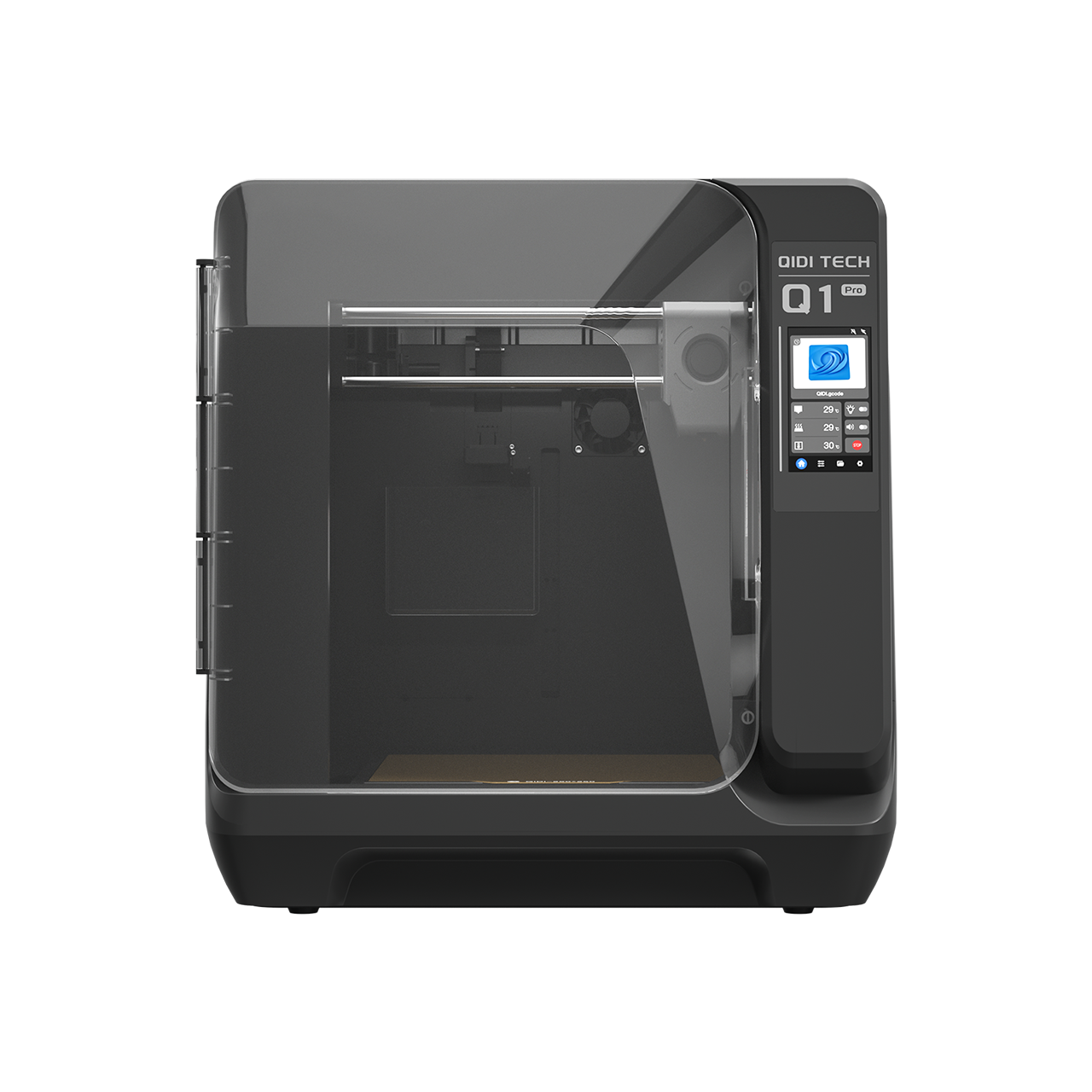
- Print on the QIDI Q2, Plus 5 or Max4 with chamber heating for the most consistent layer adhesion — the layer bond is the property that fatigue attacks.
- Use a brim on flat mounting surfaces to prevent warping during the print.
For maximum strength, print slowly (40–50 mm/s) at the upper end of PETG's temperature range. Higher temperatures and slower speeds improve interlayer bonding, which is where cycling mounts fail. The common filaments collection has PETG in various colours if you want the mount to match your bike.
Where to find models
Parametric models are worth more than fixed STLs here, because the one dimension you cannot guess is your own handlebar:
- Customizable GoPro Handlebar Mount (Thingiverse) — parametric, adjustable diameter and arm length.
- j-h-a/go-pro-mounts (GitHub) — parametric OpenSCAD models with documented interface geometry. Useful as a reference even if you prefer another CAD tool.
- Instructables clamp mount build — a full write-up with measurements, good for understanding the geometry before you modify anything.
Whatever you download, print the finger interface alone first. Ten minutes of print time confirms the fit before you spend two hours on a mount that doesn't clip on.
Always use a tether
A printed mount can break. Expect it, plan for it. A 154 g camera at 40 km/h on pavement is something you do not want bouncing into traffic or under someone's wheel.
Run a safety tether from the camera's thumb screw mounting point to your bike frame or handlebar. Commercial camera tethers are short coated steel wire lanyards, sold in multipacks for a few dollars. Cheap insurance against losing an expensive camera — and, more importantly, against putting hard debris on the road behind you.
Two more habits worth building: inspect the mount before each ride the way you would check a quick-release, and replace it on a schedule rather than on failure. Given the cycle counts above, a mount that has done a season has earned its retirement. For other outdoor gear where the same durability logic applies, see 3D printed camping gear and ABS vs ASA for outdoor structural mounts.
Frequently asked questions
What is the best filament for a bike camera mount?
PETG. Compared with PLA it offers 10–11 % elongation against 5.18 %, and 25–39 kJ/m² impact resistance against 18 kJ/m². It bends before it breaks, which gives you a visible warning instead of a sudden snap.
Will a PETG mount survive a crash?
It will probably break, which is the behaviour you want. You want the mount to sacrifice itself rather than gouging you or the bike. The tether catches the camera, and a replacement costs a couple of dollars in filament and about ninety minutes of print time.
Can I use PLA if I only ride in cool weather?
Temperature isn't the main issue. PLA fails from vibration fatigue, not heat. A season of riding is on the order of seven million load cycles in the 2–30 Hz band, and PLA propagates micro-cracks along layer boundaries under exactly that kind of loading. PETG costs the same. Use PETG.
How tight should the GoPro finger interface be?
Snug enough that the camera doesn't rattle, loose enough that you can insert and remove it by hand. Start with the STL as-is. If it is too tight, add 0.1 mm horizontal expansion in your slicer. If too loose, the thumb screw handles the rest — a properly tightened thumb screw holds the camera regardless of how tight the finger fit is.
How do I stop the clamp bolts working loose?
Use captive nuts rather than threading into plastic, put washers under both ends, and re-check after the first ride. Printed parts creep under a new clamping load, so the torque you set in the workshop is not the torque you have an hour later.
Does a stiffer filament give smoother footage?
Somewhat. PETG-CF's 3700 MPa modulus is roughly double PETG Basic's 1720 MPa, which reduces low-frequency wobble. The trade is ductility — 7 % elongation against 11.4 %. On smooth tarmac take the stiffness; on gravel take the ductility. Filament options are in the full filament collection.
- The short version
- Why the numbers say fatigue, not strength
- The GoPro mounting interface
- Get the bar diameter right first
- Mount types for cycling
- Why PETG, not PLA
- Dealing with road vibration
- Fasteners: where printed mounts really fail
- Print settings and orientation
- Where to find models
- Always use a tether
- Frequently asked questions
- What is the best filament for a bike camera mount?
- Will a PETG mount survive a crash?
- Can I use PLA if I only ride in cool weather?
- How tight should the GoPro finger interface be?
- How do I stop the clamp bolts working loose?
- Does a stiffer filament give smoother footage?
Рекомендуемые продукты