

 Q2
Q2




Improving UV Resistance for 3D Printed Trellis Connectors


Short answer: print trellis connectors in ASA, give every load-bearing section 3 mm of wall plus a 0.5 mm sacrificial surface, fillet every internal corner, and orient layer lines across the pull direction. UV does not usually break a connector by itself — it embrittles the surface, and then a wind gust or a heavy vine finds the crack that a sharp corner started.
What actually breaks a trellis connector
Photochemical degradation is a surface process. Ultraviolet photons carry enough energy to break carbon-carbon bonds in the outermost layer of the polymer, which chalks, crazes and loses its ability to stretch. The core of a 3 mm wall is largely untouched. So a connector rarely fails "because of UV" — it fails because the embrittled skin can no longer absorb a stress concentration, and layer lines plus sharp internal corners give it plenty of those. The photodegradation mechanism is worth understanding once, because it tells you where to put material.
As the Purdue University 3D printing glossary describes, FDM builds parts by fusing successive layers, and those interfaces are the weakest planes in the part. A UV-crazed surface sitting on top of a layer boundary that already carries less strength than the bulk material is the failure you will actually observe.

Put a number on the wind load
Most trellis connector guides talk about "heavy vines" and stop there. The dominant load on a vined trellis is wind, and you can calculate it. Dynamic pressure is q = ½ρv², and with air at 1.225 kg/m³ that reduces to q = 0.6125 × v² pascals for v in metres per second. Force on the panel is q × area × drag coefficient.
Worked example: a 1.2 m × 1.8 m trellis (2.16 m²) at roughly 50 % solidity once the vines fill in, so 1.08 m² of effective sail area, with a flat-panel drag coefficient of 1.2. Four connectors share the load.
| Wind speed | Beaufort | Dynamic pressure q | Force on panel | Per connector (4) |
|---|---|---|---|---|
| 10 m/s (36 km/h) | 5 — fresh breeze | 61 Pa | 79 N | 20 N |
| 15 m/s (54 km/h) | 7 — near gale | 138 Pa | 179 N | 45 N |
| 20 m/s (72 km/h) | 8 — gale | 245 Pa | 318 N | 79 N |
| 25 m/s (90 km/h) | 10 — storm | 383 Pa | 496 N | 124 N |
| 30 m/s (108 km/h) | 11 — violent storm | 551 Pa | 714 N | 179 N |
Substitute your own panel size and the Beaufort scale band your area actually sees. The numbers are smaller than most people expect, and that is the point of doing the arithmetic.
Now check whether the plastic cares
Take the 179 N per-connector figure from the storm row. If the connector's smallest load-bearing cross-section is a 10 mm × 8 mm ligament — 80 mm² — the stress is 179 ÷ 80 = 2.2 MPa. QIDI's ASA-CF20 Core data sheet lists 50.06 MPa tensile strength. That is a safety factor of roughly 22 in a violent storm.
So why do connectors break? Because 2.2 MPa is the average stress. At a sharp internal corner the local stress can be three to five times higher, and after two summers the surface that has to carry it has lost most of its ductility. The fix is geometry, not a stronger filament. Fillet the corners, thicken the ligament, and remove the notch.
Material selection with published numbers
These are QIDI's technical data sheet values from each filament's product page, for X-Y specimens.
| Material | Heat deflection temp | Tensile strength | Modulus | Elongation at break | Impact strength |
|---|---|---|---|---|---|
| ASA-CF20 Core | 101.1 °C @ 0.45 MPa | 50.06 ± 1.0 MPa | 4503 ± 103 MPa | 1.64 ± 0.11 % | 5.76 ± 0.17 kJ/m² |
| PETG-CF | 77 °C | 57 MPa | 3700 MPa | 7 % | 30 kJ/m² |
| PETG-GF | 76 °C | 51 MPa | 2400 MPa | 8 % | 35 kJ/m² |
| PETG Rapido | 70 °C | 47 MPa | 2000 MPa | 10 % | 39 kJ/m² |
| PETG Basic | 71.8 °C | 45.2 ± 4 MPa | 1720 ± 100 MPa | 11.4 ± 1.8 % | 25 ± 3.5 kJ/m² |
| PLA Basic | 57.6 °C | 34.74 ± 4 MPa | 2200 ± 100 MPa | 5.18 ± 1 % | 18 ± 2 kJ/m² |
The elongation column is the one that decides a trellis connector. ASA-CF20 Core breaks at 1.64 % strain — it is stiff and dimensionally excellent but it will not bend out of trouble. PETG Rapido stretches to 10 % and absorbs 39 kJ/m². A gust does not load a connector gently; it snaps it.
The practical compromise: unfilled ASA for the weathering, with generous fillets to compensate for its lower ductility than PETG. Use the composite grades only where the connector must hold an alignment tolerance — a sliding joint, a hinge pin boss — and accept that you are trading impact tolerance for stiffness.
Why ASA beats PETG outdoors even though PETG is tougher
ASA replaces ABS's butadiene rubber phase with an acrylate ester. The butadiene is the part that photo-oxidizes; the acrylate does not, which is why ASA was developed for automotive exterior trim and garden furniture rather than as a general-purpose filament.
A 2023 study exposed PLA, PETG, ABS and ASA — three brands of each — to five degradation regimes: UV lamp at 20 h and 100 h, a condensation chamber at 100 % humidity and 55 °C for 100 h, 130 freeze-thaw cycles from −18 °C to 21 °C, 100 h at 60 °C, and 98 days of real outdoor weather. ASA's properties were "least affected by individual factors", with no significant influence on ultimate strength across most exposures. PLA lost up to 28 % of its tensile strength in the condensation chamber alone.
Note what the freeze-thaw regime represents for a garden structure: 130 cycles of −18 °C to 21 °C is one temperate winter. If your connectors go up in spring and you inspect them next spring, that is the exposure they have already survived — or not.
For lightweight trellis frames where mass matters, ASA-Aero lets you modulate density by nozzle temperature via on-demand foaming. Use it for spacers and non-structural clips, not for the load path — foaming means voids, and voids in an outdoor part hold water.
Design rules that survive a second summer
Wall thickness: structure plus sacrifice
Split the requirement in two. The structural wall is whatever your load calculation demands. On top of that, add 0.5 mm of sacrificial thickness on every sun-facing surface, because that is roughly the depth that chalks and crazes first. For a typical stake-to-rail connector that lands at 3 mm total — set it as 7 perimeters at 0.42 mm extrusion width, not as a wall-thickness field, so the slicer cannot round it down.
Fillets, everywhere
R ≥ 2 mm on every internal corner in the load path. This is the highest-value change on the list and it costs nothing in material or print time. A sharp corner multiplies local stress; an embrittled sharp corner is a crack waiting for a windy Tuesday.
Orientation
Print so that layer lines run across the direction of pull, not along it. If the load tries to separate layers, you are testing interlayer adhesion — the weakest property the part has. If the load runs along the extrusion path, you are testing the filament itself.
Moisture before printing
Both ASA and PETG are hygroscopic. As the UTHSCSA filament reference notes, moist filament pops during extrusion and leaves microscopic voids. Those voids are entry points for water, and water that freezes inside a part expands. QIDI's published drying settings: ASA-CF20 Core at 60–70 °C for 4–6 h; PETG Rapido at 60–65 °C for 5–8 h; PETG-CF at 65 °C for 5–8 h. Keep the spool under 15 % RH during the print.
| Parameter | Value | Unit | Why |
|---|---|---|---|
| Structural wall | ≥ 2.5 | mm | Carries the calculated wind and vine load |
| Sacrificial surface allowance | +0.5 | mm | Depth that chalks and crazes first |
| Internal fillet radius | ≥ 2 | mm | Removes the stress concentration that cracks start from |
| Infill | 40, gyroid | % | Isotropic — load direction changes with wind direction |
| Nozzle temperature (ASA-CF20 Core) | 250–280 | °C | QIDI TDS; maximises layer fusion |
| Bed temperature (ASA-CF20 Core) | 90–100 | °C | QIDI TDS |
| Chamber | enclosed, actively heated | — | Reduces the thermal gradient that locks stress in |
| Filament humidity | < 15 | % RH | Prevents steam voids that later hold water |
Printing environment
Prusa's ASA page notes significant warping and styrene fumes as the two things to plan around, and recommends an enclosure for larger parts. An actively heated chamber does more than stop corner lift: by reducing the temperature gradient through the part while it builds, it reduces the locked-in stress that later combines with UV embrittlement to crack a connector.
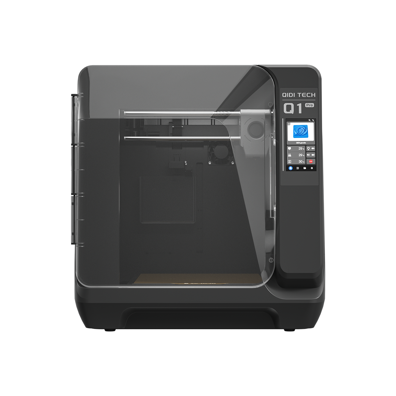
The QIDI Plus 5 (320 × 320 × 300 mm), QIDI Max4 (390 × 390 × 340 mm) and QIDI Q2 all run a 65 °C actively heated chamber. Note that the entry-level Q2C has a flame-retardant enclosure but no chamber heater, which makes it a PETG machine for this job rather than an ASA one.

Post-processing: a second line of defence
An automotive-grade UV-blocking clear coat is designed to protect car paint from exactly the radiation that degrades printed plastic, and it works on a printed part for the same reason. Apply it soon after printing, before dust and moisture settle into the layer lines, and re-coat when the gloss goes. Treat it as a consumable, not a permanent fix.
Annealing is the other option. For PETG-Tough, a slow, supported anneal relieves internal stress so the part is less prone to environmental stress cracking. Anneal a test coupon first and measure it — parts contract along the print direction and expand across it, which moves screw hole spacing.
Inspection beats prediction
Nobody can tell you how many seasons a connector will last, because that depends on your latitude, your orientation, your vine mass and your winter. What you can do is inspect on a schedule and catch the failure before it drops a fruiting vine:
- Every spring, before the growth starts: flex each connector by hand. A healthy ASA part gives slightly. A degraded one feels dead and makes a faint crackling sound.
- Look for chalk. Rub a sun-facing surface with a dark cloth. White powder means the surface layer has gone — the sacrificial allowance has done its job and is now used up.
- Check the fillets with a loupe. Hairline crazing at an internal corner is the pre-failure signal.
- Replace in sets. Connectors on the same trellis have the same exposure history. If one is done, the others are close behind.
Frequently asked questions
Which filament is most UV resistant for garden parts?
ASA. In a five-regime degradation study covering UV, condensation, freeze-thaw, heat and 98 days outdoors, ASA was the material least affected across the board. PETG is tougher on impact but yellows and embrittles under sun faster.
How much wind load does a trellis connector actually take?
Less than most people assume. For a 1.2 × 1.8 m panel at 50 % solidity with four connectors, each connector sees about 45 N in a near gale and about 179 N in a violent storm. On a 10 × 8 mm ligament that is 2.2 MPa — a safety factor over 20 against ASA-CF20 Core's 50 MPa tensile strength. Connectors fail at stress concentrations, not from average stress.
How thick should a trellis connector be?
Structural wall of at least 2.5 mm plus 0.5 mm of sacrificial surface on sun-facing faces, set as an explicit perimeter count. Fillet all internal corners at R ≥ 2 mm.
Does a clear coat really help?
Yes, as a sacrificial surface layer — it takes the UV dose instead of the polymer. It is not permanent. Plan to re-coat, and do not let a coating substitute for choosing a weather-stable base material.
Can I use PETG if I don't have an enclosure?
For shaded or seasonal structures, yes — PETG Rapido at 47 MPa and 39 kJ/m² is a genuinely tough connector material, and it prints on any machine. For a permanent full-sun installation, the UV difference will decide it. Our comparison of PETG vs ASA for permanent outdoor clamps works through the same trade-off on drip systems, and ASA vs PETG in direct sunlight covers the weathering mechanism.
What about connectors that slide or pivot?
Those need dimensional stability more than ductility, which is where the composite grades earn their place — see choosing filament for wear-resistant sliding connectors and, for parts under constant vibration, why some filaments fail in vibrating mounts. For a broader outdoor material comparison, see ABS vs ASA for outdoor structural mounts. Filament options are in the high-performance filaments collection.
Disclaimer: This article is for informational purposes only. The wind-load figures above are worked examples using standard dynamic-pressure arithmetic and assumed panel dimensions, not an engineering assessment of your structure. Longevity of printed parts depends on local UV index, orientation, printer calibration and load. Test critical structural components before relying on them, and inspect them each season.
- What actually breaks a trellis connector
- Put a number on the wind load
- Now check whether the plastic cares
- Material selection with published numbers
- Why ASA beats PETG outdoors even though PETG is tougher
- Design rules that survive a second summer
- Wall thickness: structure plus sacrifice
- Fillets, everywhere
- Orientation
- Moisture before printing
- Printing environment
- Post-processing: a second line of defence
- Inspection beats prediction
- Frequently asked questions
- Which filament is most UV resistant for garden parts?
- How much wind load does a trellis connector actually take?
- How thick should a trellis connector be?
- Does a clear coat really help?
- Can I use PETG if I don't have an enclosure?
- What about connectors that slide or pivot?
Рекомендуемые продукты