Q2
Q2


Why Your 3D Printed Knobs Don’t Fit the Shaft Properly


Why Your 3D Printed Knobs Don’t Fit the Shaft Properly
It is a scenario we see frequently on the repair bench: you spend an hour meticulously measuring a potentiometer shaft with digital calipers, design a replacement knob with 0.01mm precision in CAD, and wait two hours for the print to finish. Yet, when you try to slide the knob onto the D-shaft or spline, it refuses to budge. Or worse, it slides on but wobbles with enough play to make the interface feel cheap and unreliable.
For prosumers and small shop owners, this isn't just a minor annoyance—it is a loss of billable time and material. Achieving a "factory feel" in functional spare parts requires moving beyond hobbyist trial-and-error. To produce parts that fit the first time, you must account for the complex interplay of polymer physics, slicer geometry, and thermal management.
The Physics of Internal Hole Shrinkage
The primary reason a 6.0mm hole in CAD rarely results in a 6.0mm hole in reality is the nature of thermoplastic cooling. As the printer extrudes a circular path, the plastic naturally wants to pull toward the center of the arc as it contracts. This effect is magnified in internal diameters compared to external dimensions.
Material-Specific Shrinkage Variables
Different materials exhibit vastly different shrinkage rates, which are further influenced by the cooling rate. Based on our observations in functional part production:
- ABS/ASA: These materials typically exhibit a shrinkage rate of 0.5% to 0.7%. However, if the cooling is uneven, this can lead to "differential shrinkage," where the top of the hole is tighter than the bottom.
- Nylon (PA): Semicrystalline materials like Nylon are notorious for high shrinkage, often ranging from 1.2% to 1.8%.

Managing Geometric Complexity: D-Shafts vs. Splines
The geometry of the shaft itself dictates the tolerance strategy. A standard D-shaft is relatively forgiving, but splined shafts (common in automotive and high-end audio) present a "stair-stepping" challenge.
The D-Shaft Strategy
For a standard D-shaft, we typically recommend a clearance of 0.15mm to 0.25mm. The "flat" side of the D-shaft acts as the primary torque transfer point. If the fit is too tight, the stress is concentrated on the corners of the "D," which can lead to crack propagation in materials like PLA. For these applications, using a high-performance material like PA12-CF Filament is highly effective because its carbon fiber reinforcement significantly reduces XY shrinkage and increases impact resistance.
The Spline Challenge
Splines require more breathing room—usually 0.3mm to 0.4mm. Because 3D printers approximate curves with small segments, the "teeth" of a printed spline are often slightly larger than the CAD intent. Furthermore, the Ultimaker material guide on PETG vs PLA vs ABS highlights that impact-resistant materials can slightly deform under load, which is actually beneficial for splines as it allows the teeth to "seat" themselves.
The Role of Temperature Control in Dimensional Accuracy
One of the most overlooked factors in part fitment is the ambient environment. If you are printing engineering-grade materials in an open-frame printer, you are fighting a losing battle against physics.
Why Enclosed Chambers Matter
Dimensional stability requires a consistent chamber temperature throughout the entire print cycle. Warping and shrinkage are directly tied to the rate at which the part cools.
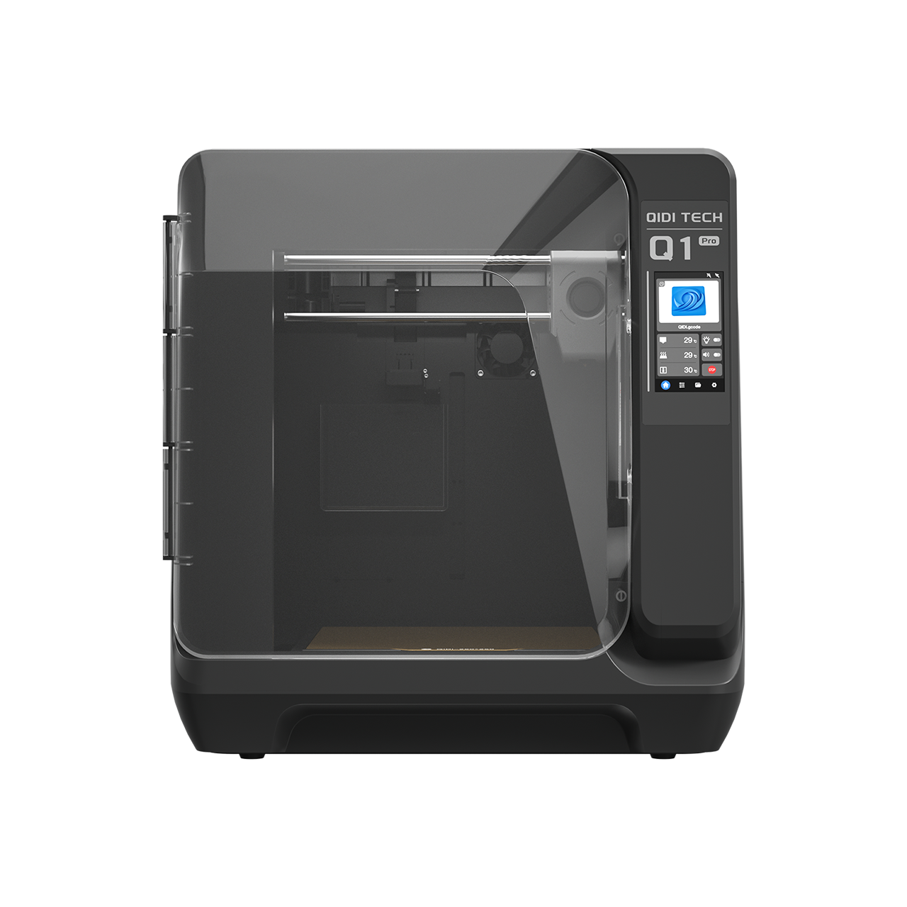
In our testing, using a printer with an active heated chamber, such as the QIDI Q2 3D Printer which maintains a 65°C environment, reduces differential shrinkage by approximately 30% for ABS and ASA. This ensures that the bottom of the knob (near the heated bed) and the top of the knob have nearly identical hole diameters. Without this control, you often end up with a "tapered" hole that fits at the entrance but jams halfway down the shaft.

Slicer-Level Solutions for Better Fitment
Before you reach for the drill bit, there are three critical settings in your slicer that can solve 90% of fitment issues.
- XY Hole Compensation: Most modern slicers allow you to specifically expand internal diameters without affecting the outer dimensions of the part. A value of 0.1mm is a standard starting point for 6mm shafts.
- Elephant’s Foot Compensation: The first layer is often squashed to ensure bed adhesion, creating a "lip" that narrows the hole entrance. We recommend combining a 0.2mm horizontal expansion compensation with a 45° chamfer at the base of the hole in your CAD design.
- Wall Ordering: Set your slicer to print "Outer Wall First." While this can slightly degrade overhang performance, it ensures the nozzle isn't pushing against existing inner walls, which can "bulge" the hole inward.
For parts that require extreme UV resistance or will be used outdoors, ASA Filament is the preferred choice. If weight is a concern—for example, in drone or aerospace applications—ASA-Aero Filament uses on-demand foaming technology to reduce part weight by up to 50% while maintaining the dimensional benefits of the ASA base.
Professional Post-Processing: The "Final Fit"
Even with perfect settings, engineering materials can be unpredictable. If a part is just too tight, professional practitioners use two primary methods to achieve a perfect fit without reprinting:
- Step-Drilling: Using carbide bits in 0.1mm increments allows you to clean out a bore with surgical precision. Always drill at a low RPM to prevent the plastic from melting and seizing the bit.
- Controlled Thermal Expansion: A brief application of a heat gun (aimed at 85-95°C) can soften the internal walls just enough to allow you to press-fit the knob onto the shaft. Once it cools, the plastic will "shrink-wrap" around the shaft, creating an incredibly secure interface.
Summary Checklist for Perfect Fitment
- Measure the shaft: Use the actual hardware, not just the datasheet.
- Select the right material: Use PA12-CF Filament for high-torque mechanical parts.
- Control the environment: Utilize a heated chamber (like the 65°C chamber on the QIDI Q2 3D Printer) to ensure vertical uniformity.
- Apply compensations: Use XY Hole Compensation (0.1mm) and Elephant Foot offsets.
- Design for the process: Add 45° chamfers to all hole entrances.
By treating 3D printing as a thermal management challenge rather than just a geometric one, you can produce spare parts that rival—and often exceed—the quality of original injection-molded components. Whether you are replacing vintage furniture knobs or creating custom mechanical spacers, precision is the hallmark of professional work.
Disclaimer: This article is for informational purposes only. When creating replacement parts for high-torque, high-heat, or safety-critical applications, always perform thorough load testing. 3D printed parts may have different failure modes than original components.
- Why Your 3D Printed Knobs Don’t Fit the Shaft Properly
- The Physics of Internal Hole Shrinkage
- Material-Specific Shrinkage Variables
- Managing Geometric Complexity: D-Shafts vs. Splines
- The D-Shaft Strategy
- The Spline Challenge
- The Role of Temperature Control in Dimensional Accuracy
- Why Enclosed Chambers Matter
- Slicer-Level Solutions for Better Fitment
- Professional Post-Processing: The "Final Fit"
- Summary Checklist for Perfect Fitment