How to 3D Print Interlocking Parts and Assemblies

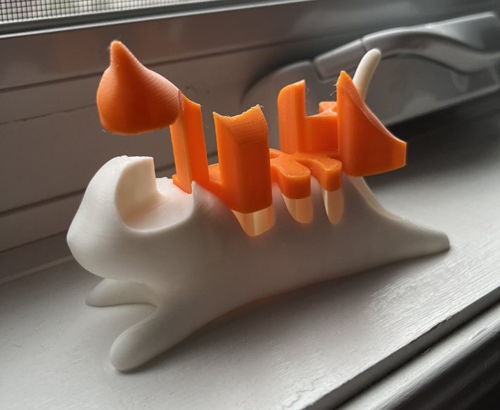
You remember that feeling when you finish a 3D print and realize you need screws, nuts, and bolts to put it all together. Good news: you don't have to anymore. With the right technique, you can print snap, slide, and lock-together parts without any extra hardware. This tutorial covers the doable tips that actually work for creating everything from simple snap-fit boxes to movable assemblies.
The Basics of Interlocking 3D Prints
What Exactly Are Interlocking Parts?
Interlocking parts are 3D printed components that connect with their shape only—no screws, adhesives, or fasteners needed. These designs utilize sharp geometry to form connections from permanent to allowing movement.
Common examples you might recognize:
- Snap-fit containers that click shut
- Gears that rotate against each other
- Boxes with thin, flexible hinges
- Puzzle-like pieces that slide and lock together
Interlocking designs are more efficient in that they save you time by precluding the necessity to find the appropriate hardware. Interlocking designs give you a cleaner look with no visible screws or bolts, enable quicker testing and iteration of your designs, and save you money by avoiding the need to purchase additional parts. For all makers, being able to simply print and assemble is reason enough to master these methods.
Essential Concepts for Success
Clearance and Tolerances
The most important concept to master is clearance—the intentional gap between parts that allows them to fit together properly.
| Fit Type | Typical Clearance | Best For |
| Loose | 0.2-0.5mm | Parts that move freely (hinges, rotating joints) |
| Nominal | 0.1-0.2mm | Parts that slide with some resistance |
| Press | 0-0.1mm | Parts that should stay connected but can be separated |
| Interference | Negative clearance | Permanent connections |
Key Point: Always design with clearance in mind. A perfect fit in your CAD software will often be too tight in the real print.
Material Properties

Different materials create different results with interlocking parts:
PLA: Good starting point
✓ Precise dimensions
✓ Rigid connections
✗ Can be brittle
✗ Poor for parts that flex during assembly
PETG: Great all-rounder
✓ More flexible than PLA
✓ Good for snap-fits
✓ Durable connections
✗ Can be stringy, affecting precision
TPU/Flexible: Special applications
✓ Perfect for living hinges
✓ Excellent for parts that need to flex
✗ Challenging to print precisely
✗ Not suitable for rigid connections
Beginner Tip: Start with PLA for your first interlocking designs. Once you understand the basics, try PETG for more robust connections.
Printer Calibration
Before attempting any interlocking parts, ensure your printer is properly calibrated:
- Bed Leveling - Foundation of print accuracy
- E-steps - Ensures correct amount of filament
- Temperature - Find the sweet spot for your material
- Flow Rate - Fine-tunes dimensions
Remember: Even the best design will fail if your printer isn't properly calibrated. Take time to get these basics right first.
Once you master these fundamentals, you'll be ready to explore specific joint types and design techniques.
How to Design Interlocking 3D Prints That Connect Without Hardware
Two Essential Connection Types for 3D Prints
You don't need to master dozens of joint types to create functional 3D printed assemblies. Focus on these two connection methods that solve nearly all interlocking needs: snap-fits and press-fits.
Snap-Fit Connections
Snap-fits create that satisfying "click" when parts come together. These connections work well for assemblies that need to stay secure but might require occasional opening.
Building on the clearance principles discussed in the first section, snap-fits represent a practical application where a flexible hook or tab temporarily bends during insertion, then springs back behind a ledge to lock in place.
Advanced dimensions for production-quality snap-fits:
- Hook length: At least 2× the hook thickness (longer for high-stress applications)
- Hook thickness: Minimum 1.2mm for PLA, can be reduced to 0.8mm for PETG's greater flexibility
- Clearance: Apply the 0.2mm minimum clearance principle specifically to side walls and non-connecting surfaces
- Entry angle: 30-45° for easy insertion (shallower angles for frequent assembly/disassembly)
- Retention angle: 90° for secure locking (60-75° for easier disassembly)
Common problems and solutions:
- Hooks breaking during assembly: Increase hook length or use more flexible material
- Connection too loose: Reduce clearance or increase hook engagement depth
- Too difficult to assemble: Increase entry angle or add more pronounced lead-in chamfers
Press-Fit Connections
Press-fits represent another application of proper clearance design, but with an inverse approach—intentionally creating controlled interference rather than gaps. These clean connections are ideal for components that need precise alignment or rotation.
Material-specific size differences for different functional needs:
- PLA: Pin 0.1-0.2mm larger than hole (0.1mm for rotating fits, 0.2mm for static connections)
- PETG: Pin 0.05-0.15mm larger than hole (lower values due to its greater compliance)
- ABS: Pin 0.1-0.15mm larger than hole (ideal for heat-set applications)
Design Tip: A 45° chamfer on pin ends dramatically improves assembly. For stronger connections, increase contact surface area rather than tightening the fit tolerance.
Press-Fit Connections
Press-fits represent another application of proper clearance design, but with an inverse approach—intentionally creating controlled interference rather than gaps. These clean connections are ideal for components that need precise alignment or rotation.

Material-specific size differences for different functional needs:
- PLA: Pin 0.1-0.2mm larger than hole (0.1mm for rotating fits, 0.2mm for static connections)
- PETG: Pin 0.05-0.15mm larger than hole (lower values due to its greater compliance)
- ABS: Pin 0.1-0.15mm larger than hole (ideal for heat-set applications)
Design Tip: A 45° chamfer on pin ends dramatically improves assembly. For stronger connections, increase contact surface area rather than tightening the fit tolerance.
1. Create the Basic Container Structure
Start with a rectangular box using 2mm walls for small containers. Create a matching lid with the same wall thickness. Size the lid to overlap the box with exactly 0.2mm clearance on all sides to prevent friction while maintaining a clean appearance.
2. Add Snap Features to Box and Lid
On the box, create 4mm wide, 1.5mm thick tabs at the center of each wall with a 45° lead-in angle on top. For the lid, design matching 4.4mm wide pockets with a small 0.5-1mm lip above each pocket for the tabs to lock behind. This provides 0.2mm clearance on each side for smooth assembly.
3. Optimize the Design for Strength
Add 45° chamfers to bottom edges and round internal corners with at least 0.8mm radius to prevent stress concentration. Orient critical structural elements to account for the directional strength properties of printed plastic, placing layers perpendicular to expected force directions.
4. Create a Test Piece Before Final Production
Design a small test model with just one connection point and several clearance variations (0.1mm, 0.2mm, 0.3mm). This quick test saves time and material while allowing you to verify dimensions before committing to the full design.
Design Techniques That Prevent Assembly Problems
1. Use Symmetrical Connections
Have all the points of connection identical around your design wherever possible. This is simpler to test, results in similar assembly behavior, saves time on the design, and delivers the same results. If one good connection works, they will all work.
2. Add Assembly Guidance Features
Supply alignment ridges to guide components into place before snap features are engaged. Form asymmetrical interfaces where components must align in specific manners. Apply visual indicators like arrows or symbols to show proper alignment immediately.
3. Plan for Disassembly
Build small recessed areas where tools can apply leverage safely without damaging anything. For frequently opened parts, design special release mechanisms that catch at moderate pressure. Test the process of taking apart to ensure connections withstand heavy use.
Pre-Print Verification Checklist
✓ Clearance Implementation: Verify that the general clearance principles from Section I are correctly applied to your specific design—0.1-0.2mm for mating surfaces, adjusted based on your printer's calibration results
✓ Material-Appropriate Dimensions: Ensure structural elements meet the material-specific thickness requirements (1.2mm for PLA hooks, 0.8mm for PETG, etc.)
✓ Overhang Assessment: Connection areas print cleanly without difficult support removal, especially critical for precise mating surfaces
✓ Structural Proportions: Apply the mechanical principles by ensuring hooks maintain a length:thickness ratio of at least 2:1 (3:1 for higher reliability)
✓ Assembly Ergonomics: All insertion points have appropriate lead-in features like chamfers or tapers to guide parts together naturally
How to 3D Print Interlocking Parts Successfully
After designing your interlocking parts, proper printing settings are essential for creating pieces that fit together perfectly.
Essential Printer Calibration
Bed Leveling for Dimensional Accuracy
Use the "paper method" for manual leveling - a standard sheet should barely drag under the nozzle at multiple points. For automatic systems, run a multi-point mesh calibration and verify with a test print before attempting precision parts.
E-Steps Calibration for Material Flow
Mark 100mm of filament, extrude 50mm, and measure the remaining distance. Calculate:
New e-steps = Current e-steps × (50 ÷ Actual distance extruded)
Temperature Settings for Connection Parts
| Material | Nozzle Temp | Bed Temp | Notes |
| PLA | 195-200°C | 50-60°C | Lower temps for precision |
| PETG | 230-240°C | 70-80°C | Better for flexible tabs |
| ABS | 235-245°C | 100-110°C | Requires enclosure |
| TPU | 220-230°C | 40-50°C | Print very slowly |
Print Speed for Feature Precision
Reduce speed by 30-50% for interlocking features. Use 20-25mm/s for connection features and 30-40mm/s for internal structures. Critical snap-fit tabs should print slower than the main body.
Key Slicer Settings
Layer Height for Detail
For precise snap-fits with small features, use a 0.1-0.12mm layer height to capture fine details and ensure dimensional accuracy. Most interlocking parts work well at 0.16mm, offering a good balance between detail and print time. Reserve 0.2mm layers only for larger press-fits with clearances greater than 0.3mm, as the coarser resolution may affect critical dimensions of smaller features.
Wall Settings for Durability
Configure 3-4 perimeters for snap-fit features to ensure they can withstand repeated flexing, while 2-3 perimeters typically suffice for container walls. When printing the 1.5mm thick snap tabs designed for our box example, use at least 3 perimeters with a 0.4mm nozzle to provide proper strength during the bending action of assembly and disassembly cycles.
Infill for Function
Set infill density according to the mechanical requirements of different parts. Snap-fit tabs benefit from 30-40% infill to balance strength with the necessary flexibility for insertion. For the main container body, 15-25% infill provides adequate structural support without excessive material use. The gyroid pattern offers an efficient strength-to-material ratio and works particularly well for parts that need to flex without breaking.
Support Strategy for Clean Connections
Orient your parts to minimize supports on mating surfaces whenever possible. When supports cannot be avoided, increase the Z-distance to 0.2mm and reduce support density to 10-15% for easier removal without damaging critical surfaces. Enable a support interface with a concentric pattern to create a buffer between the support structure and your part, resulting in cleaner connection surfaces.
Horizontal Expansion for Perfect Fit
Fine-tune clearance using your slicer's horizontal expansion settings to compensate for printer-specific variations. For tight press-fits, apply negative expansion between -0.05mm and -0.1mm to create additional clearance. Conversely, for loose snap-fits, apply positive expansion of +0.05mm to +0.1mm to tighten the connection. When working with multi-part assemblies, take advantage of per-model settings to selectively adjust only specific components.
Optimal Print Orientation
For Snap-Fit Features
Position tabs so layers run parallel to their length, not across them. This orientation makes tabs up to 60% stronger during flexing as they won't separate along layer lines.
For Press-Fit Connections
Print pins with their long axis vertical for the most accurate diameters. Print holes with their axis parallel to Z whenever possible for better circularity.
For Sliding Surfaces
Orient prints so layer lines run parallel to the sliding direction to reduce friction during assembly and operation.

How to Assemble and Finish Your Printed Parts
Even the best designed parts need proper finishing to work well together. This section covers the practical steps to get your parts from the printer to a working assembly.
Cut and Twist Supports Away from Connection Points
Use sharp flush cutters to snip supports at their base, then twist them away from the part. For snap-fit tabs, cut supports at multiple points first, then roll them away along the tab's length—never pull straight out or you'll break the tab. For complex parts where manual removal is too risky, consider using dissolving supports: PVA (dissolves in water) works with PLA/PETG while HIPS (dissolves in limonene) pairs well with ABS prints.
Sand Connection Surfaces and Apply Proper Lubricant
Sand connection areas progressively (220-grit then 400-600 grit), always moving in one direction and testing fit frequently to avoid removing too much material. Add a tiny dab of silicone grease on snap hooks for easier assembly, or use dry graphite powder for rotating parts since it won't get sticky or attract dust. For stubborn ABS or PETG parts (never PLA), briefly apply gentle heat from a heat gun (8-10 inches away for 3-5 seconds) to temporarily increase flexibility during assembly.
Press and Rock Parts Together Using Even Pressure
Align parts correctly and apply even pressure, listening for the satisfying "click" of snap-fits when properly seated. For the example box, start pressing at the corners and work toward the middle of each side. When dealing with tight press-fits, use a gentle rocking motion instead of forcing parts straight together; if they still won't connect, apply a small amount of bar soap as a temporary lubricant that won't damage the plastic.
Fix Tight, Loose, or Breaking Connections
Parts too tight? Either sand mating surfaces slightly, or go back to your slicer and add -0.05mm horizontal expansion. Check if your printer is over-extruding, which makes parts larger than designed.
Parts too loose? Your printer might be under-extruding, or the design needs less clearance. Try adjusting positive horizontal expansion (+0.05mm) in your slicer or increase the depth that hooks engage.
Parts breaking during assembly? Make the hooks longer compared to their thickness (aim for at least 2:1 ratio), check your print temperature for good layer bonding, or change the print orientation so layer lines run along the length of flexible parts.
Design Your First Interlocking Project!
Creating interlocking 3D prints eliminates the need for screws and bolts, resulting in cleaner, faster-to-assemble projects. By focusing on proper clearances, appropriate materials, and careful printing techniques, you can produce parts that fit together perfectly. Remember that success usually comes after a few test pieces—document what works for your specific printer and materials. With these techniques, your 3D printer becomes more than just a prototyping tool; it delivers complete, functional objects without the hardware hunt.


 Q2
Q2
 QIDI Box
 Plus 4
 Q1 Pro
 X-Max 3
