
 Q2
Q2
 QIDI Box
 Plus 4
 Q1 Pro
 X-Max 3


Glass Effect? Tips for 3D Printing with Transparent Filaments
This guide provides key slicing techniques for achieving glass-like transparency when 3D printing with PETG filament, focusing on parameters like high flow, temperature, slow speed, and specific infill patterns to minimize layer lines and light scattering.
To 3D print transparent parts on an FDM machine, print PETG at 260-270 °C with the cooling fan at 0%, one wall loop, zero top and bottom shells, 100% aligned rectilinear infill, 0.5 mm line width and 20-40 mm/s. The goal is to eliminate the air gaps between extrusion paths, because every gap scatters light and turns clear plastic milky.
With its balanced mechanical properties, print compatibility, and transparency, transparent PETG has become the top choice for FDM 3D printing of transparent models. Due to the layer-by-layer stacking principle of FDM, issues like inter-layer gaps and path clearances that affect light transmittance are inevitable. With careful adjustments, however, it is still possible to create transparent models with stunning results.
This tutorial summarises the techniques for printing high-transparency PETG models, mainly from the perspective of slicing parameter settings. I have printed a lot of failed cloudy cubes getting to these numbers, so the section on why it goes wrong is there for a reason.
Transparent PETG Settings at a Glance
Start here, then read the reasoning below. These values are for QIDI PETG Translucent on a 0.4 mm nozzle; the material's published window is 240-280 °C nozzle and 70-80 °C bed, and these settings sit deliberately at the hot, slow end of it.
| Setting | Value | Why |
|---|---|---|
| Nozzle temperature | 260-270 °C | Hotter melt flows into the gaps between adjacent paths and welds them shut |
| Bed temperature | 70-80 °C | QIDI's published range for the PETG series |
| Part cooling fan | 0% | Slow cooling lets each path fuse into the one beside it before it freezes |
| Print speed | 20-40 mm/s | Compensates for the missing fan; also reduces flow pulsing |
| Flow ratio | +2% to +5% over calibrated | Slight over-extrusion fills residual voids between paths |
| Line width | 0.5 mm on a 0.4 mm nozzle | Fewer paths means fewer interfaces to scatter light |
| Wall loops | 1 | Every extra loop adds another vertical interface |
| Top / bottom shells | 0 / 0 | Shell layers cross the infill direction and create a diffuse haze |
| Infill | 100%, aligned rectilinear, 0° or 90° | All paths parallel, so light crosses the fewest possible boundaries |
| Layer height | 0.2-0.3 mm | Thicker layers mean fewer horizontal interfaces (see the trade-off below) |
| Drying before printing | 55-65 °C, 4-6 h | QIDI's published drying spec for PETG; moisture makes bubbles, and bubbles are opaque |
Why FDM Prints Come Out Cloudy
PETG resin itself is clear. What makes a printed part milky is not the plastic, it is the geometry inside it. Wherever two extruded paths sit side by side without fully fusing, a thin air void is left between them. Light crossing from plastic into air and back changes direction at each boundary because the two materials have very different refractive indices, and thousands of those micro-boundaries add up to diffuse light scattering. That scattering is what your eye reads as haze.
Every setting in the table above is aimed at the same target: fewer boundaries, and better fusion at the boundaries that remain. That is why a single wall, zero shells, aligned 100% infill and a switched-off fan all pull in the same direction. Once you see it that way, the settings stop looking like a random list and start looking like one idea applied nine times.
Schematic Diagrams
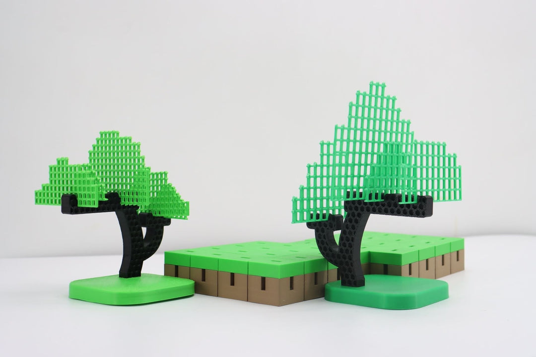
- Transparent Cube:

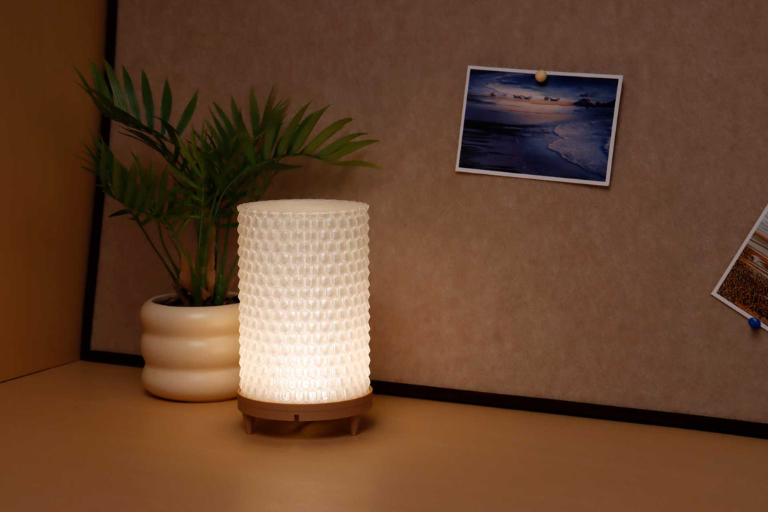
- Transparent Lampshade:

Step-by-Step Guide
1. Pre-Printing Preparation
Filament Drying
When printing with damp filament, the interior or surface of the model is prone to bubbles or severe stringing. A bubble is a void, and a void scatters light, so wet filament costs you transparency directly rather than just cosmetically. Dry the spool at 55-65 °C for 4-6 hours before you start — that is QIDI's published spec for the PETG series — or enable the drying function of the QIDI BOX during printing, which holds the spool at a constant 65 °C for the whole job. The full temperature chart for every material is in the filament drying guide.
Build Plate Selection
If you need to print a light-transmitting model, use a smooth build plate so the bottom surface of the model is also smooth. A textured PEI sheet transfers its pattern into the first layer and that pattern scatters light exactly like an internal void does. On a Q2 the dual-sided smooth plate is the right choice here.
Nozzle Selection
A larger nozzle means wider lines and fewer printing paths, thereby reducing the gaps between paths. This tutorial uses a 0.4mm nozzle as an example, but the nozzle is one of the biggest single levers you have:
| Nozzle | Line width used | Paths across a 20 mm wall | Clarity | Detail retained |
|---|---|---|---|---|
| 0.4 mm | 0.5 mm | 40 | Good | Best |
| 0.6 mm | 0.7 mm | 29 | Better | Good |
| 0.8 mm | 0.9 mm | 22 | Best | Coarse on small features |
QIDI's own recommendation for maximum light transmission on the PETG Translucent series is a 0.8 mm nozzle. Roughly half as many paths means roughly half as many internal boundaries. The cost is resolution: fine text, thin ribs and small snap features stop resolving cleanly. For a lampshade or a light pipe, take the 0.8 mm. For a display cube with an embossed pattern, stay at 0.4 mm and get the clarity back in post-processing instead.
2. Filament Settings

Increase Flow Ratio
Moderately increasing the flow ratio reduces flow fluctuations during printing, lowers the risk of clogging, and minimises gaps between lines. Add 2-5% over your calibrated value and no more. Push past about 8% and the extra material has nowhere to go, so it piles up as ridges on the top surface and you lose more clarity than you gained.

Raise Nozzle Temperature
A higher nozzle temperature allows PETG to melt more fully, resulting in better adhesion between paths. The recommended nozzle temperature for QIDI PETG TRANSLUCENT series filaments is 240-280 °C. For transparency, run at 260-270 °C — the upper part of the window, but not the very top, because above about 275 °C PETG starts to degrade and yellow slightly on long jobs.

Turn Off Cooling Fan
Set the fan speed to 0 so the filament cools naturally, preventing the uneven shrinkage that rapid cooling causes. Correspondingly, reduce printing speed in the process settings. Slow cooling also matters for a second reason: PETG is a slow-crystallising polyester, and holding it warm keeps it in the amorphous state that transmits light. Rapid quenching promotes polymer crystallisation, and crystalline domains scatter light just as voids do.

3. Process Settings
Layer Height and Line Width
Adjust the layer height according to the characteristics of the model:
- A smaller layer height is beneficial for optimising the surface smoothness of the model and reducing light scattering when light enters and exits. It suits models that will be sanded and polished, and thin-walled models.
- A larger layer height reduces internal gaps within the model, improving basic light transmittance and printing efficiency.
The two pull in opposite directions, so pick by which surface matters. Light entering through a face you will polish anyway wants thick layers and fewer internal boundaries. Light entering through a face you will leave as printed wants thin layers and a smoother skin.
Uniformly adjust the line width to 0.5 mm, which helps reduce printing paths and unnecessary gaps.

Walls and Infill
- Set the number of wall loops to 1.
- Set the number of top shell layers and bottom shell layers to 0.
- Use 100% density aligned rectilinear infill, and set the direction to 0° or 90°.
Aligned rectilinear matters more than people expect. The default alternating ±45° pattern crosses every layer over the one below at 90°, which means light travelling through the part meets a boundary every single layer. Locking the angle to one value makes those paths stack directly on top of each other, so the boundaries line up into continuous columns instead of a grid.


Speed
Use a slow printing speed (20-40 mm/s) to give each layer of filament sufficient time to adhere. This is the setting people most want to skip, and skipping it is why their cube came out foggy. With the fan off, speed is the only thing controlling how long a path stays molten next to its neighbour.

After printing is completed, wait for the build plate to cool before removing the model, which helps maintain the smoothness of the model's bottom surface.
QIDI Q2 PETG Settings for Transparent Prints
The Q2 has one feature that helps here more than any slicer tweak: a second-generation independent chamber heater that holds 65 °C. A warm chamber does the same job as switching the fan off, but across the whole part rather than just at the nozzle, so the part cools slowly and evenly from top to bottom. On an open-frame printer the lower layers cool much faster than the upper ones, and that gradient shows up as a clarity gradient.
| Q2 setting | Transparent PETG value | Note |
|---|---|---|
| Nozzle | 260-270 °C | The Q2 bimetal hotend runs to 370 °C, so this is well inside its range |
| Bed | 70-80 °C | Bed maximum is 120 °C; no need to go near it |
| Chamber | 50-65 °C | Set it and let the part cool slowly. This is the single biggest clarity gain |
| Speed | 20-40 mm/s | Ignore the 600 mm/s headline figure; transparency is not a speed job |
| Part cooling fan | 0% | With the chamber warm this is safe even on overhang-free geometry |
| Build plate | Smooth PEI side | Textured side stamps a light-scattering pattern into layer one |
The same settings transfer to any QIDI machine with an actively heated chamber. Note the one exception in the lineup: the entry-level Q2C has a flame-retardant enclosure but no chamber heater, so on that machine you rely on the closed enclosure plus a switched-off fan rather than a set chamber temperature.
Troubleshooting Cloudy Transparent Prints
| What you see | Most likely cause | Fix |
|---|---|---|
| Uniform milky haze throughout | Voids between paths | Raise nozzle 10 °C, flow +3%, fan to 0%, speed down to 25 mm/s |
| Tiny bubbles suspended inside | Wet filament | Dry at 55-65 °C for 4-6 h, then print from a sealed dry box |
| Cloudy only near the build plate | First layers cooled too fast, or textured plate | Smooth plate, raise chamber or bed, slow the first five layers |
| Clear body, foggy top surface | Top shells enabled, or over-extrusion ridges | Top shells to 0; if already 0, reduce flow toward +2% |
| Visible grid pattern in the light | Alternating infill angle | Aligned rectilinear, single direction, 0° or 90° |
| Yellow tint on long prints | Nozzle too hot for too long | Drop to 260 °C; do not exceed 275 °C on multi-hour jobs |
| Stringing across open areas | Moisture plus zero fan | Dry the spool; add a small retraction increase rather than fan |
Post-Processing: Where the Last 30% of Clarity Comes From
No FDM setting removes the layer lines on the outside of the part, and those lines scatter light on the way in and on the way out. Post-processing addresses that surface, and it is where a good print becomes a genuinely clear one.
- Wet sand progressively. 400, then 800, then 1500, then 2000 grit, with water, keeping the surface flooded. Skipping grits leaves scratches the next grade cannot remove.
- Polish. Plastic polish or automotive headlight compound on a soft cloth, worked until the surface reflects cleanly.
- Or coat instead. A clear gloss spray fills the remaining micro-roughness with a material of similar refractive index, which is why a coated part looks clear immediately. Two thin coats beat one thick one; a thick coat sags and adds its own distortion.
The sanding sequence is the same one used on opaque prints, so the technique in the sanding and polishing guide transfers directly. If the end goal is a lamp or a diffuser, note that you often do not want maximum clarity — see the notes on choosing translucent filaments for lamp shades, where a controlled amount of optical haze is the point rather than the problem. Light-driven decorative prints such as colour lithophanes use the same transmission physics from the other direction.
FAQs About Transparent 3D Printing
How do you 3D print transparent PETG?
Dry the spool, then print at 260-270 °C with the part cooling fan at 0%, one wall loop, zero top and bottom shells, 100% aligned rectilinear infill at a single angle, 0.5 mm line width and 20-40 mm/s. On an enclosed printer set the chamber to 50-65 °C. Sand and polish or clear-coat the outer faces afterwards for the final step in clarity.
Can you get truly glass-clear parts from an FDM printer?
Not straight off the plate. Optically flawless parts need a process without internal interfaces, which FDM inherently has. What is realistic is a part that reads as clear at arm's length, transmits light well enough for lamps and light pipes, and becomes genuinely see-through once the outer surfaces are polished or coated. Thin walls do far better than thick blocks, because there is less material for scattering to accumulate through.
Is PETG or PLA better for transparent prints?
PETG. It is an amorphous polyester that stays optically clear as it solidifies, it has a wide temperature window that lets you run hot for path fusion, and it is tougher than PLA so thin clear walls survive handling. Clear PLA can look good on very thin parts but goes hazy faster in thicker sections and is more brittle.
Why is my transparent print white or milky?
Air voids between extrusion paths, in almost every case. Raise the nozzle temperature, add a few percent of flow, turn the fan off and slow down — those four changes together fuse the paths and remove the boundaries. If tiny distinct bubbles are visible rather than a uniform haze, the cause is moisture instead and drying is the fix.
Does infill density matter for transparency?
It is decisive. Anything below 100% leaves engineered air gaps inside the part, and air gaps are the exact thing that makes it opaque. Use 100% density, aligned rectilinear, locked to one direction. The full range of clear and translucent options is in the PETG series.
Conclusion
3D printing transparent models with FDM is an interesting exercise that rewards patience with the parameters. Everything comes back to one principle: remove the interfaces inside the part, and smooth the interfaces on its surface. Get the settings above in place, dry your filament, print slow with the fan off, and then finish the outer faces by sanding, polishing or coating to take the result the rest of the way.